Chapter 5
The VTR
Quadruplex and Helical Scan Recording
As we've mentioned, the largest VTRs may be the size of two refrigerators and could cost $200,000 or more. These are the big QUAD format machines that use 2-inch wide videotape and produce the best quality color pictures.
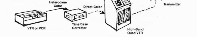
Quad or QUADRUPLEX VTRs reside mainly in TV broadcasters' studios and require expensive human and technical support systems. Basically, the quad is a 4-head video recording system that produces pictures on the tape by scanning the videotape at a 90° angle as it travels by at high speed-15 IPS (inches per second). One roll of 1-hour quad tape costs $250-S300. The quad is an expensive animal to feed.
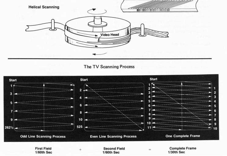
The other type of video recording process is known as HELICAL SCAN RECORDING. Invented by Toshiba Corporation of Japan in 1953, helical scan utilizes a screw-like scanning process that places the video information DIAGONALLY along the tape. The helical scan mechanism uses only 1 or 2 heads, is much simpler than the quad process, and moves the tape along much slower—from 9 to 11/2 ips. This slower rate of tape travel and the use of smaller tape greatly reduces tape consumption and operational and maintenance costs of helical scan recording relative to quad recording.
Tape size or width determines the TAPE FO R-MAT. A particular VTR is designed for one particular tape format only. At present, there are 5 different tape formats-2-inch, 1-inch, 3/4-inch, 1/2-inch and 1/4-inch. A 3/4-inch wide videotape can only be used with a VTR specifically designed to use 3/4-inch tape. Thus the VTR becomes known as a 3/4-inch VTR or a 3/4-inch format VTR.
None of the different tape formats are compatible with any other format and in some cases, there is no compatibility even within the same format. For example, Sony has manufactured three different yet incompatible 1-inch VTR formats. It sounds crazy, but don't despair.
Although you can't take a 1/2-inch tape which was recorded on a '/2-inch VTR and play it back on a 1-inch VTR, it's quite possible electronically to TRANSFER or COPY the tape to any other size VTR format. In this case, you are making a SECOND GENERATION copy of the tape which will probably suffer a slight quality loss but still be quite acceptable. So, even though VTRs may not be physically compatible, they are all electronically compatible, especially with the help of a time base corrector.

|
|
|
VTR USE TABLE |
| |
|
TAPE |
|
|
|
|
|
FORMAT |
|
|
|
COST |
|
(Size) SCAN TYPE |
MODE |
WHERE USED |
HOW USED WHY USED |
RANGE PORTABILITY |
|
2-inch Quadruplex |
High-band |
Broadcast TV |
Over-the-air Excellent color |
$100,000 None—Except for |
|
R-to-R |
color Low-band color |
studios—NBC, CBS, ABC, PBS, local TV stations, large universities |
broadcasting. quality To make multiple Very high picture copies & go many definition. ' generations Easily edited |
and up special suitcase model Ampex VR-3000 |
|
|
|
|
Very flexible |
|
|
2-inch Helical scan |
b&w and |
Broadcast TV |
Editing Good to excellent |
$100,000 Somewhat |
|
R-to-R |
color |
Schools, univer- |
Large closed- quality picture |
to $60,000 portable, no field |
|
|
|
sities, industry |
circuit systems Good copies |
model |
|
1-inch Helical scan |
b&w and |
Schools, industry, |
For anything Moderate to excel- |
$1800 to Excellent porta- |
|
R -to-R |
color |
professions, cable |
recordable— lent quality pic- |
$60,000 ble field models |
|
|
|
TV, Broadcast TV |
For copies of all ture, and editing tape |
|
|
h-inch Helical scan |
b&w and |
Schools, industry, |
Videocassettes Standardized |
$1,300 to Excellent |
|
U-Matic |
color |
professions, cable |
Master recording Good quality color |
$7,000 portable units |
|
standard videocassette |
|
TV, home use |
Editing 2 sound tracks National (stereo sound) |
|
|
|
|
|
Distribution Easy to use |
|
|
|
|
|
Excellent editing |
|
|
1/2-inch Helical scan |
b&w and |
Schools, industry, |
Videocartridge Standardized |
$800 to Highly portable, |
|
EIAJ |
color |
professions, cable |
Teaching, experi- Low cost |
$2,300 excellent field- |
|
standard R-to-R |
|
TV, home use |
mental, closed Easy maintenance circuit, surveil- Simplicity, good lance, anything editing |
model portapaks |
|
1/2-inch |
b&w and |
Home, schools |
Record Low-cost tape |
$900 to Compact |
|
Video- cassette |
color |
industry |
off-the-air, Distribution |
$1,600 field models |
|
'3/4-inch Helical scan |
b&w and |
Homes, schools, |
Teaching, home Low cost |
$900 to Excellent, |
|
R-to-R |
color |
Cable TV |
use, on-location Small size recording, distri- Light weight bution limited by nonstandardization |
$2,500 highly portable |
A Comparison of Film and Audio Recording
There are 2 common methods of recording picture and sound—chemically, as in film recording, and electronically, as in video recording. In the first process, the film image undergoes a chemical change in reaction to light. In the second instance, the video image and audio elements undergo an electronic conversion from light and sound to voltage and magnetism.
Since video and audio are both electronic media, they bear a closer relationship to each other than video does to film. It is important to realize that the video recording process evolved from the audio recording process rather than from the film recording process.
THE VTR RECORDING PROCESS Recording Heads
Like an audio recorder, a recording VTR uses a series of magnetic RECORDING, ERASE and PLAYBACK HEADS. These heads contain electromagnetic coils which when energized, create a magnetic field in the coil. This in turn causes the magnetic particles on the videotape to respond and store the electronic information.
The VTR is unique because it employs special rotating VIDEO HEADS which record and play back the picture component of the electronic information. The video heads are made up of tiny magnetic coils with a small gap between them.

Unlike stationary audio heads, video heads will not work if they are standing still. Instead, video heads must rotate at a high speed, in the opposite direction to the tape travel. This rotation is apparent when the VTR is placed in PLAY or RECORD mode and a pronounced whirring sound is heard emanating from the video head drum.
Inside the Video Head Drum
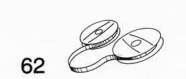
On all 1/2-inch EIAJ VTRs, two video heads are used, one located on each end of a bar which is mounted on a circular rotating plate.
The head bar rotates at 1800 rpm (revolutions per minute) if it has 2 record/play video heads, and 3600 rpm if it has only one record/play video head—as is the case with many 1-inch VTRs.
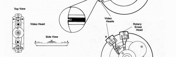
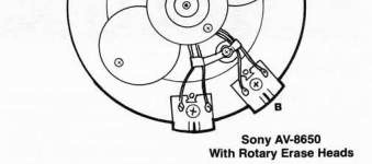
Sophisticated editing VTR s such as the Sony AV-8650 and VO-2850 and the Panasonic NV-3160 employ 4 rotating video heads-2 heads to record and to play back the picture, and 2 additional erase heads mounted just ahead of the record/play heads to insure that erasing of the old picture information is complete right up to the point of the new recording. The stationary erase head is still used, but the distance between the rotating video heads and the stationary erase head can prevent precise editing of the new picture. Therefore, ROTARY ERASE HEADS are used to insure perfect erasure of old picture information right up to the point of the new edit. In 3/4- inch videocassette recorders, the video heads are integrated into the rotating head drum itself. This system is simpler and has fewer problems. Some new generation 1-inch VTRs (Ampex and Sony) also use 1 or 2 additional heads, as well as the flying erase and record/playback heads for improved tracking, broadcast quality slow-motion and for monitoring playback during recording.
The Rotating Video Head
Video heads must rotate at high rates of speed because of the necessity to record and reproduce the very wide range of frequencies required by the video picture. Even the most sophisticated of stationary recording heads used in high quality audiotape recorders can record and play back only 20 to 20,000 Hz. HERTZ (Hz) is the official designation for cycles per second. Video, however, requires a range of 2.5 MHz (million, or MEGA-HERTZ) for black-and-white, and 3.5 to 4.5 MHz for color—or 18 octaves! Frequency response is traditionally extended in several ways:
-
improve the electronics and the tape
-
increase the size of the tape
-
increase the speed of the tape past the head

Early attempts to record video information on tape involved the use of 2-inch wide tape traveling 50 to 100 inches-per-second (ips) past stationary video heads. Obviously the economics of this approach was not encouraging, as the VTR was huge and the tape costs were astronomical.
Then some creative thinking produced the idea of moving the video head at high rates of speed counter to the tape direction, thus creating a very high relative TAPE-TO-HEAD or WRITING SPEED. The writing speed for quad is 1000 to 1500 ips at a TAPE SPEED of 15 ips, and about 700 ips is the writing speed for U-Matic at a tape speed of 3-3/4 ips. Low-cost VTR s now could become a reality.
NOTE: Since the video heads do rotate at high speed and actually contact the moving videotape, use only good quality proper videotape and keep the video heads clean. The video heads usually are made out of FERRITE, a material which has excellent frequency response but is brittle and will damage easily. Therefore, no hard articles should lie placed on or near the video heads, especially if they are still rotating.
Replacement of video heads for 1/2-inch or 3/4- inch VTR s will cost approximately 5150, including labor. With proper care, cleaning and use of good tape, video heads should last for 2 or 3 years of frequent use. Sony claims 1000 hours life expectancy for its video heads.
|
Tape Size |
Tape Speed/Size/Cost Comparison Format Tape Speed 60 Min. of Tape |
Cost | ||
|
2-inch |
quad |
15 ips |
4800 ft. |
$300 |
|
1/2-inch |
EIAJ |
7 ips |
2400 ft. |
35 |
|
34-inch |
U-Matic |
3 3/4 ips |
1200 ft. |
30 |
|
1/2-inch |
Betamax |
11/2 ips |
480 ft. |
15 |
|
1/2-inch |
Beta-2 hr. |
0.785 ips |
240 ft. |
7 |
VTR Mechanics
-
Speed Control—Every VTR must have a multiple configuration of erase, record and playback heads. The VTR also must have a very precise speed control system because proper VTR speed is critical to picture stability and quality.
-
SYNC—Besides the picture and sound, there is a third consideration when recording a videotape, the synchronization or SYNC PULSES that must accompany the picture corn
ponent. These sync pulses are horizontal and vertical pulses or signals usually generated from the video camera and always accompany the video picture. The sync pulses permit the scanning system to reconstruct the video picture on the TV monitor. These pulses are ENCODED or combined with the video picture during recording and playback. The combination of sync and picture elements (video) is called a COMPOSITE VIDEO SIGNAL.

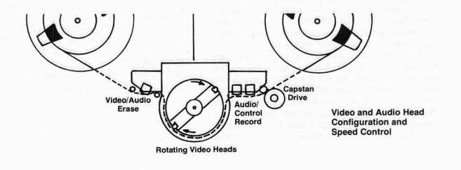
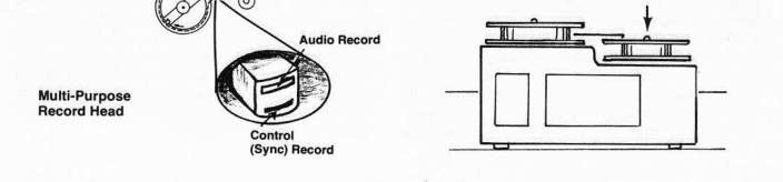
3. Control Track—The VTR also records special CONTROL TRACK PULSES on the tape through a CONTROL TRACK HEAD, usually a separate track on the audio record or erase head. The control track pulses help the VTR maintain proper speed, which is critical to accurate playback of sync pulses.
The control track pulses on the videotape are often referred to as "electronic sprocket holes," to draw a film recording parallel. These pulses are regularly spaced along the videotape and will greatly affect the quality of the playback picture if the control-track head becomes clogged or malfunctions. The movement of the tape through the VTR is mechanically controlled by the CAPSTAN DRIVE.
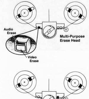
Multi-Purpose Heads
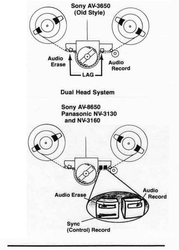
Often a single head will combine 2 different functions. All Sony 1/2-inch VTR s except the AV-8650 perform both audio and video erase on one stationary head and audio record and control-track record/playback on a second head. This allows editing of the sound without affecting the video. All recording VTRs can do this.
Unfortunately, because of the distance between the audio erase head and the audio record head, there is an annoying audio lag when editing on machines like the Sony AV-3650. Panasonic VTR sand the Sony AV-8650 place a third stationary head that performs audio erase right next to the audio record head. The audio lag is then eliminated.
Helical Diagonal Tape Scanning
A distinguishing characteristic and one of the more curious aspects of helical scan VTRs is the different levels at which the tape reels are placed. One side is always considerably higher than the other side.
On most EIAJ 1/2-inch VTR s, the left SUPPLY-REEL side is always about 1 inch higher than the right TAKE-UP-REELside. Because of this height difference, the tape will travel through the VTR on an angle. The rotating video heads are mounted in a flat plane thereby contacting the tape in a screw-like (helix) diagonal fashion and creating more surface contact.
Unlike film, the video image is made up of 525 horizontal lines. The scanning electron beam in the camera tube and in the CRT (TV tube) scans every other line, or half the total number of lines (262Y2) in 1/60th of a second, odd lines first. Then, the beam goes back and scans all the even lines in the same amount of time (1/60th of a second). Each set of 2621/2 lines is called one FIELD, and the two fields are INTER LACED to make one 525-line FRAME. 30 complete frames are scanned each second—a rate fast enough to give the eye a sense of continuous motion. 16 mm film operates at only 24 frames per second, so the difference in FRAME RATES causes a
Each of the diagonal lines scanned across the tape by the rotating video heads represents a specific amount of picture information. The method of laying down the video tracks on the tape is determined by the way the video or TV scanning system process works.
black line to appear in the picture when you are filming a TV set in operation.
If a VTR uses a SEGMENTED recording system, it will have 2 video heads—one head per field of information. If it is NON-SEGMENTED, it will have only 1 head which must record and play back both fields. In a 2-head VTR, every time a video head scans the tape, one field of information is recorded or recovered from the videotape. When you look at a single "frame" of tape, all you really see is one field. This is why the quality of a still frame is never as good as the moving tape image, because then you are seeing fields interlaced together as complete frames.

During the scanning process, horizontal and vertical sync pulses are generated to tell the electron beam to scan the picture correctly both horizontally and vertically. These pulses keep the picture straight from top-to-bottom and from side to side. The combination of sync pulses and video information (composite video) is then placed on the videotape by the two rotating video heads.
The video heads in a 2 head VTR will make 1800 revolutions per minute or one pass with each
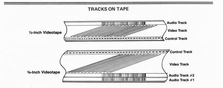
head every 60th of a second. As previously stated, since the tape travels past the heads on a diagonal, each field of information is placed on the tape diagonally, thus permitting more information to be stored by the tape. The video portion of the tape requires approximately 85%, and the audio and control tracks take up much of the remaining 15% so the tape cannot be reversed to record on the other side as audiotape can.
The Audio Track
The AUDIO TRACK is usually located on the top part of the tape. Because it is on the same tape as the picture, the sound always will be in perfect sync with the picture at all times. Unfortunately, 1/2-inch and 1/4-inch videotape has only enough room to allow one audio track. Larger formats fit 2 or more audio tracks on the tape, permitting added editing flexibility and the capability to record stereo sound. New-generation 1-inch and broadcast 3/4-inch and 2-inch VTRs have a third audio (or CUE TRACK) for recording special TIME-CODE information, used in editing for reference to individual frames on the tape.
The Control Track
The control track contains the control track pulses which regulate the speed of the VTR and the rate at which the tape is moved through the VTR. Very precise speed control is necessary for proper reproduction of the original recording. First, the rotating video heads must align perfectly with the video tracks on the tape. The heads also must simultaneously utilize the corresponding control-track pulses which will insure the correct picture playback.
Alignment of the video heads with the tape tracks is called TRACKING. This is the source of many VTR play-back problems. If the tape guides are misadjusted, the head-drum sticky or dirty, control-track head out of alignment or the speed of the VTR is not precise, the tape will not play back very well.
The TRACKING CONTROL on VTRs is designed to compensate for some differences in video head alignment relative to the video tracks. If you have problems of this nature, have your VTR checked with a manufacturer's special ALIGNMENT TAPE.
Stretching of the tape will distort both the timing of the control track pulses and the reading of the video information. FLAGGING, or bending problems then will result at the top of the picture during playback. The SKEW or tape tension control on the VTR can be used to minimize this situation somewhat. Extreme problems will require that the tape be processed by a time base corrector.
SOME INTERESTING STATE-OF-THE-ART VTR RECORDING SYSTEMS The Azimuth Recording System
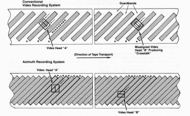
Normally, the diagonal tracks that the video heads scan across the tape must have small separations (GUAR DBANDS) between them, so a slightly misaligned video head does not accidently pick up the information from an adjacent track. The undesirable interference of a signal from an adjacent track is called CROSSTALK.
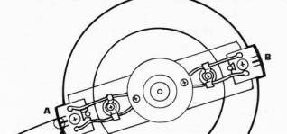
Since these separations between the tracks wasted valuable recording space, Sony engineers set out to remedy the situation. They ingeniously devised a way to utilize the empty spaces between the tracks by slightly offsetting or angleing the video heads at 7° to each other. Thus the heads could record an individual track that could be sensed only by that same head because of its angle or AZIMUTH. In this manner, head "A" can pick up only information on track "A," and head "B" can sense only information on track "B," even if the heads become misaligned. If the heads pass over the wrong tracks, no signal will be produced because the head will be out of phase with the track's information.
Elimination of guardbands allows more information to be stored on a narrower tape width. The Azimuth Recording System was designed specifically for use with the Betamax and Beta 2-hour VTR formats and represents another significant step forward in VTR evolution.
The Azimuth Recording System, as used on the Betamax, does reproduce surprisingly good color video for a VTR that moves the tape past the heads at such a slow speed. This seems to be the direction in which VTR designs are moving—slower tape speeds for economy, but with improved picture quality. Achieving both these goals simultaneously is like creating a bigger and faster automobile that also gets more miles per gallon. But the Japanese always have been able to create seemingly impossible technology?
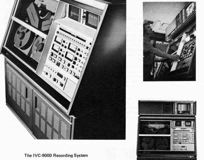
International Video Corporation (I VC), an innovative American video company noted for its excellent line of 1-inch VT Rs, has conceived and developed a 2-inch helical scan broadcast TV master-production VTR that exceeds the quality performance of a quad VTR, yet uses only one-half the amount of tape.
The IVC-9000 VTR uses 2 rotating video heads (segmented scan) which strike the tape at a diagonal angle of 19.55°. This reduces the head-totape impact by 18:1, compared with a quad head which must strike the tape at a 90° angle. The picture quality and performance of the IVC-9000 is truly incredible and the machine itself really looks spacey.

General Features of the IVC-9000:
•Uses HOT PRESSED FERRITE (HPF) video heads which have better frequency response than the metal heads of quad VTR s.
-
Performs well on all 3 TV standards—NTSC, PAL and SECAM
-
Has a wide variety of tracks
•A II tracks can be edited simultaneously in any combination, or individually.
•The control track is located in the stationary section of the head drum, so the 300-Hz control track pulse is recorded directly beneath the corresponding video track—not later at some distance from the SCANNER (the video head drum) where differences in tape tension can affect tracking.
-
Fast, accurate tape handling. Precision mechanics and controls provide tape movement speeds continuously variable from 2 to 300 ips in forward or reverse. This permits rapid and efficient search for locations of specific edit points on the tape.
•The tape transport and scanning mechanism are completely enclosed in a positive pressure environment fed by filtered air. Vacuum columns constantly clean the tape by drawing air across it and removing loose debris and dust particles.
Tape Economics—Because the IVC-9000 uses helical scan 2-inch videotape, the cost is less per foot than quadruplex videotape. The higher efficiency of the HPF heads permits scanning of a greater number of video tracks per square inch than in the quad method. The IVC-9000 has a tape speed of 8 ips and can record the same amount of information on slightly more than one-half the amount of tape used by a 15 ips quad VTR. A minimum of 2 hours of program material can be recorded on a 101/2-inch reel of videotape. Lower tape cost, less tape-per-unit time, and less tape storage space adds up to an economic advantage for the IVC-9000. Of course, it is a beautiful piece of engineering and a high-priced machine intended for use by broadcast TV stations. Videotapes made on this machine can be played back only on another IVC-9000.
Plug-in modules (Models IVC-9000-4 and IVC9000W) are available for the basic IVC-9000. They can convert it to 4 hour recording capacity or SUPER -HIGHBAND 8 MHz frequency-response (IVC-9000W). The IVC-9000W can be used for tape-to-film transfers where very high resolution (700 lines b&w, 500 lines color) is necessary. The conversion module IVC-9000M will allow the 8MHz version to operate at a 655-line 48-field rate which enables it to interface with the film industry's standard 24 frames-per-second rate. This version should improve the tape-to-film transfer system significantly.
COLOR VTRs
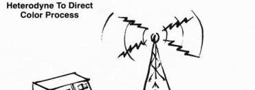
The Heterodyne Color Process
It isn't really too difficult for a black-andwhite VTR to record color. Only a few extra steps and circuits are needed. But the design of small-format VTR s-1/2-inch, 3/4-inch and 14-inch does not make it possible to process directly the very high (3.58 MHz) COLOR SUBCAR R I ER required by the color picture. A method therefore was devised to reduce the color frequency to only 267 KHz (KI LOHERZ is thousand cycles) which the small-format VTRs could record easily. This process of reduction is called HETERODYNING and nearly all Japanese color VTRs use the HETERODYNE COLOR PROCESS if they fall into the class of LOW-BAND VTRs. LOW BAND means they can record only a small, limited bandwidth (about 2.5 MHz) or frequency response.
The Heterodyne color process also requires separation of the chrominance and luminance elements of the picture. Upon playback, the 767 KHz signal again is boosted to 3.58 MHz. Because the phase of the color in the 767 KHz subcarrier is not locked to the horizontal frequency of the video signal, heterodyne color does not meet FCC broadcast standards and cannot be played directly over the air.
The Direct Color Process
So called HIGH-BAND 1-inch or 2-inch VTRs are capable of much better frequency response characteristics and are able to record easily the 3.58 MHz signal directly. These VTRs are called DIRECT-COLOR VTRs. All 2-inch quad VTRs are high band VTRs and can record and play direct color only. If you are transferring a tape from 1/2-inch or 14-inch VTR to quad, the heterodyne color must be converted to direct color. This usually is done by placing the appropriate time base corrector (TBC) between the small-format heterodyne VTR and the direct color quad VTR. Most TBCs can change the heterodyne color of the small-format VTR to direct color for direct overthe-air broadcasting or transfer to a 2-inch quad for copying or editing.
The Range of VTRs
The range of VTR technology is mind-boggling. Simple playback-only 1/2-inch units can be bought for S800 or less. Or, for a totally computerized quad VTR with vacuum tape-drive chambers, fantastically high-quality color and super-precise editing ability, you could spend over $250,000.
VTR technology has evolved rapidly, especially with the introduction of integrated circuits and space technology. In its wake, it has left lots of obsolete 1-inch and 1/2-inch VTRs, which are still quite adequate for simple b&w applications. These units can be purchased inexpensively and if they work okay, can be fine machines on which to learn.
So, why not provide a home for a 1-inch Ampex or Sony VTR that is sitting lonely and forgotten on a basement shelf just gathering dust?
Happily, technical advances have definitely reduced the price of good-quality color recording, playback and editing VTRs. A wide range of 3/4- inch and 1/2-inch color machines, (some very sophisticated) is available to fill nearly every video user's needs. As with cameras, you should shop around for a demonstration of a particular VTR's recording, playback and editing qualities and talk with owners of similar equipment. Make edits and copy the tape several times to see how well the color quality holds up. This will give you a good indication of the quality of the VTR.
With some understanding of VTRs, we now move on to the recording medium itself—The Videotape.