Chapter 10
Connecting And Operating The VTR
Asa preliminary to the actual "hands on" operation of the equipment, it helps to have an understanding of the various component parts of the standard VTR.
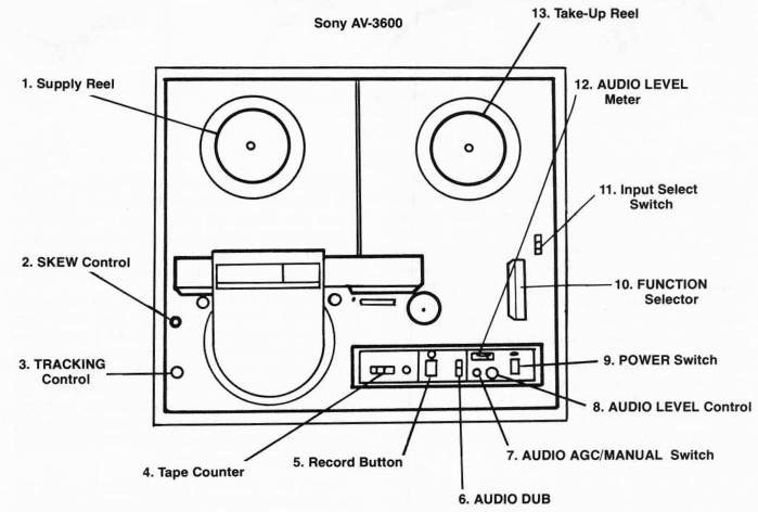
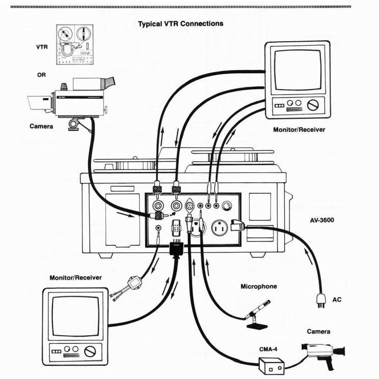
A very popular basic Y2-inch VTR is the b&w EIAJ Sony AV-3600. The controls and operational functions on this unit are similar to all the other Sony Y2-inch reel-to-reel VTR s.
Controls and Connectors—Sony AV-3600
-
SUPPLY REEL SPINDLE—Place a full reel of tape here.
-
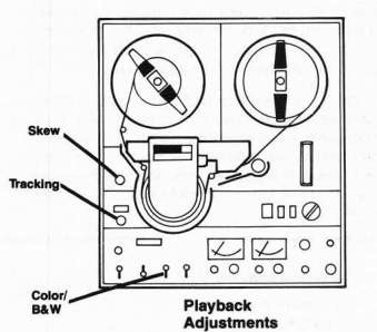
SKEW CONTROL—This control operates in playback mode only. It adjusts the tension of the videotape around the video head drum. Adjust it if the images are bent at the top of the screen. Do not turn this control while recording. See Skew Control Adjustments, page 124.
-
TRACKING CONTROL—This control operates in playback mode only. It adjusts the tracking of the VTR to compensate for differences in tapes made on other VTRs. See Tracking Control Adjustments, page 124. Do not adjust while recording.
-
TAPE COUNTER AND RESET BUTTON—The tape counter indicates the amount of tape used. Push the reset button to 000 at the start of the tape. The counter is not particularly accurate.
-
RECORD BUTTON—This button will activate in RECORD, STOP or PAUSE modes only and will cause the VTR to record picture and sound. To begin recording, depress the RECORD button and move the function selector to FORWARD mode simultaneously—use two hands. To monitor the picture and sound, depress the RECORD button when the VTR is in the STOP mode.
-
AUDIO DUB BUTTON—The audio dub control operates in playback mode only and allows new sound to be added without erasing the picture.
NOTE: The old sound is erased when the new sound is added.
-
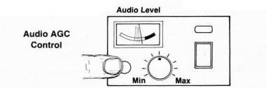
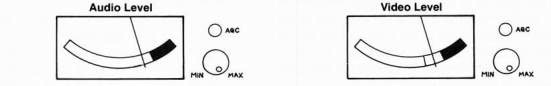
AUDIO AGC/MANUAL SWITCH—This control operates in playback mode only and allows automatic gain control (AGC) or manual control of the sound recording level. Depress the button to select manual control
-
AUDIO LEVEL CONTROL—This control operates in the manual mode only. Adjust for the proper level on the audio level meter (No. 12).
-
POWER SWITCH—Turns the VTR ON or OFF.
-
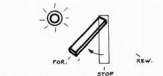
FUNCTION SELECTOR—This selector is a 5-position switch that controls the function or mode of the VTR. It always should be kept in the STOP position unless the VTR is playing or recording. The five positions are:
FAST FORWARD advances tape rapidly
PAUSE/STILL stops tape for still picture
FORWARD moves tape at normal speed for record or play
STOP stops tape
REWIND rewinds tape
-
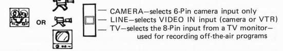
INPUT SELECTOR SWITCH—This switch operates in record mode only and selects the
appropriate input:
-
AUDIO LEVEL METER—This meter displays the audio level in record and playback modes. When recording the audio manually the needle should barely peak into the red zone on the
loudest sounds.
-
TAKE-UP REEL SPINDLE—Place an empty reel here.
Common Color VTR Controls (Color VTRs only—Sony AV-8600/AV-8650)
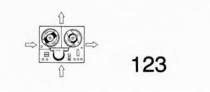
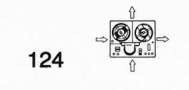
COLOR LOCK CONTROL—This control is found usually on the top of the VTR. Adjust with a small screwdriver if the VTR cannot maintain the correct color hues in the playback picture. The control should be kept in the DETENT (notched) position.
VI DEO MODE SELECTOR—Located on the top plate of the VTR, this control adjusts the VTR for either B&W or COLOR recording and playback.
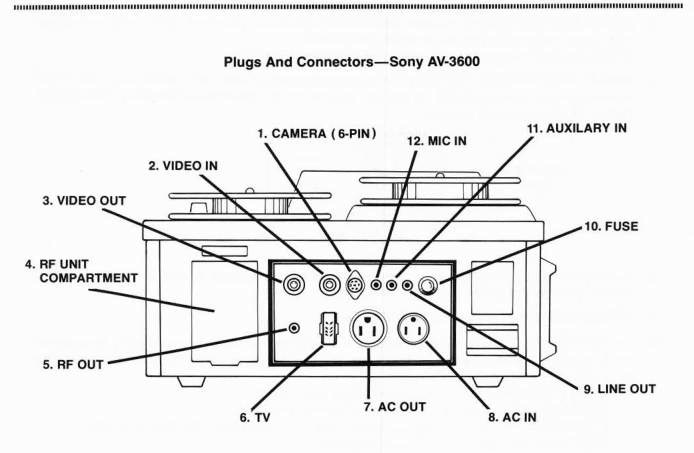
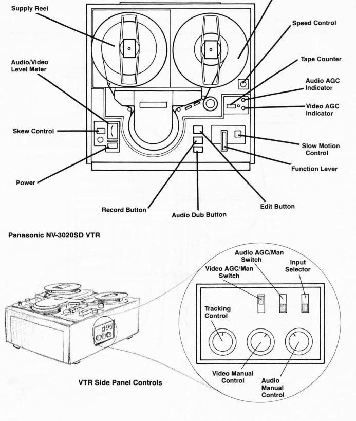
Plugs and Connectors—Sony AV-3600
-
CAMERA—Plug a 6-Pin cable in here from a Sony AVC Series camera.
-
VIDEO IN—Accepts a UHF-type cable from a camera, VTR, or monitor.
-
VIDEO OUT—Accepts a UHF-type cable. Connect to a monitor or a second VTR.
-
RF UNIT COMPARTMENT—Insert optional RF Adaptor here. Allows playback of picture and sound on a regular TV set.
-
RF OUT—Plug optional RF cable in here and connect to any TV set.
-
TV 8-PIN CONNECTOR —Use an 8-Pin cable to connect to any standard TV monitor. The 8-Pin carries sound and picture to and from the monitor.
-
AC OUT—Supplies up to 500 watts AC power to another unit, such as a monitor or camera.
-
AC IN—AC power cord connects here from any 120-volt AC 60 Hz source.
-
LINE OUT—Connect to auxiliary sound amplification, a recording VTR or a TV monitor. This output is for sound use only.
-
FUSE-2 amps—Do not use a fuse with a higher rating.
-
AUXILIARY IN—Accepts a sound input from a playback VTR, audiotape player, or microphone mixer. This input will riot accept a microphone.
-
MIC /N—Connect a good quality low impedance microphone here.
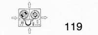
Panasonic NV-3020 SD
The Panasonic NV-3020 SD is a slightly different style b&w 1/2-inch EIAJ VTR. It offers more features than the Sony AV-3600 VTR. The NV-3020 SD incorporates a manual and AGC control of the video level, a fair quality slow motion mode, and the ability to go into record mode while the VTR is playing back. Thus a crude edit can be
made.
VTR Precautions
•The video rotary heads are delicate and brittle and will not withstand any impact with a solid object. Cleaning should be attempted only when the video heads are completely stopped.
-Operate the VTR only in a horizontal position.
-DO NOT block the ventilation grills on the bottom of the VTR or it may overheat.
-
Keep VTR clean at all times and free from dust. Keep the machine covered when it is not being used.
•AVOID subjecting the VTR to mechanical shock or vibration.
-DO NOT allow cigarette smoking anywhere near VTRs or near room air currents that might pass the VT R s.
-DO NOT handle videotape or VTRs after smoking without first washing your hands.
-
Make sure the FUNCTION SELECTOR LEVER is in the STOP mode when the VTR is not in use.
-Use the same size reels for supply and take-up reels.
-DO NOT operate the VTR in extreme temperatures.
-
Clean the VTR head drum immediately if it is exposed to salt air.
-
Have your VTR checked twice a year for proper tracking and skew specifications.
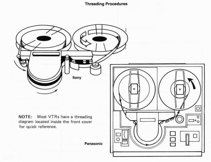
OPERATING THE REEL-TO-REEL VTR Videotape Threading Procedure
In order to record or play a tape on a reel-to-reel VTR, the videotape first must be properly threaded.
Procedure:
Step 1 Place a full reel of tape on the supply reel spindle (left side of the VTR).
Step 2 Place an empty reel on the take-up reel spindle (right side of the VTR). Make sure the take-up reel is the same size as the supply reel.
Step 3 Make sure the VTR is in the STOP MODE and that no whirring sound is coming from the video head assembly.
Step 4 Unwind about 2 or 3 feet of the tape from the supply reel.
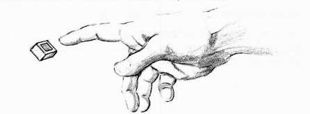
Step 5 Thread the tape from left to right as illustrated: -The dull side of the tape should face the operator. -The shiny side of the tape should face the video heads.
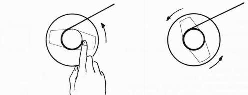
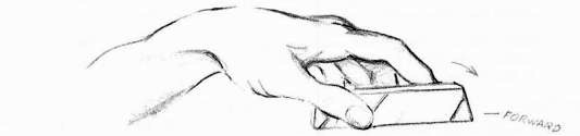
Step 6 Place a finger inside the take-up reel and hold the tape against the reel hub. Rotate the take-up reel one full turn counterclockwise until the tape slack is taken up and then remove your finger.
Step 7 Visually recheck the threading.
Step 8 Place the VTR in PLAY mode to confirm that the tape is seated on the take-up reel and threaded properly.
Tape Threading Precautions:
-NEVER thread the VTR while the video heads are slowing down, otherwise the heads may become damaged.
-
Make sure the tape is in the guide path correctly and not caught on something, otherwise the tape will become creased and useless.
-Make sure no tape guides, rollers, or little levers have been missed when threading.
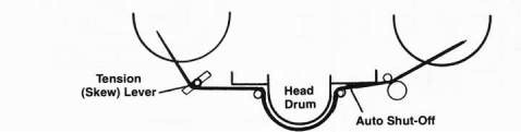
- Be sure to check the tension and automatic shut-off levers. If the tape is not threaded around the tension lever properly, the tape will not play back correctly. If the tape does not exert sufficient pressure against the automatic shut-off lever, the VTR will not operate.
Always play the VTR for a few seconds to confirm that everything is working properly. Always make a test recording and play back the tape before beginning your program taping session. Now is the time to find out if anything is wrong.
Minor Troubleshooting
- If something does go wrong, the first thing to check is the threading. Don't hesitate to re-thread the tape.
-
Remember, only the shiny side of the tape can be used for recording.
-
If the tape gets caught and slips inside the video heads, stop the VTR immediately, gently pull the tape out, taking care not to crease it. If the tape is hopelessly snagged inside the head drum, carefully remove the head drum cover and cut the bad tape out with scissors and remove it from the VTR.
Playback Procedure
First, read Instruction Manual thoroughly.
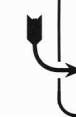
Step 1 Plug the AC power cord into the VTR and the AC outlet.
Step 2 Plug the monitor power cord into the VTR or other AC outlet.
Step 3 Plug the 8-Pin TV/VTR connector into the VTR and the TV monitor, or connect the RF unit.
Step 4 Place the videotape supply reel and the take-up reel on the VTR.
Step 5 Thread the videotape.
Step 6 Turn on the VTR and the monitor.
Step 7 Turn the TV/VTR switch on the monitor to the VTR position.
Step 8 Place the VTR in PLAY or FORWARD mode.
VTR Playback
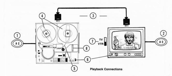
Equipment Needed:
1 VTR
1 TV monitor/receiver or TV receiver with RF Adaptor
Plugs and Wires Needed:
1 AC POWER cord for VTR
1 8-Pin connector or RF Adaptor connector
cable or 1 UHF or BNC Coax cable for
video and an audio cable for sound with
Mini, RCA or Cannon connectors.
Accessories:
1 Take-up reel
SPECIAL PLAYBACK ADJUSTMENTS
Still Picture
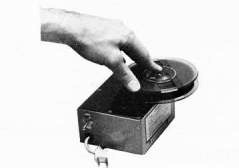
A still picture can be obtained at any time during playback by moving the FUNCTION SELECTOR LEVER to the PAUSE mode. Often a line will appear in the still picture, but it can be minimized or eliminated by hand rotating the reels until the line of distortion disappears. Do not still-frame longer than a minute or so as the tape wears excessively during still-framing, because the video heads actually touch the videotape when scanning.
NOTE: Clean still-framing can only be obtained with pictures recorded from a 2:1 INTER LACE SYNC camera. Pictures recorded from a RANDOM SYNC camera will not still frame.
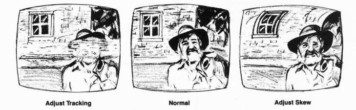
Tracking
The tracking control adjusts the VTR for tapes made on other compatible (or same format) VTRs. Observe the picture playback for excessive noise bands or distortion. Turn the tracking knob until the distortion disappears. VTRs in proper condition rarely should need tracking adjustments.
Skew
The skew control adjusts the tension of the tape against the video head drum. Adjust the skew if the top of the playback picture appears to bend to the right or to the left. Turn the skew knob to the right or to the left until the picture straightens out.
What is Skew Error?
In simple terms, skew errors result from any change in the length of the video track on the tape between the time it was recorded and the time it is played back. A skew error shows as a hooking in the picture at the top of the TV monitor during playback. If the picture hooks to the left, the video track on the tape is longer than the playback track length of the machine. If the picture hooks to the right, the video track on the tape is shorter than the playback length of the machine.
The amount of skew error will depend on the type of monitor or TV set used. The Sony Trinitron or other newer type Japanese TV sets or monitors have SHORT TIME CONSTANTS in their horizontal scanning circuits and thus will display only a slight distortion when playing back a tape containing skew errors. Older type monitors or American TV sets will bend considerably or lose horizontal lock completely. See Chapter 8—TV Monitors and Video Projectors, p. 98.
Usually there is a wide variation in tape tension (skew) from one VTR to another so the skew control must be constantly adjusted. Failure to properly adjust the skew during editing can result in serious problems to the editing tape.
Skew error can be caused by the tape or by the machine. A skew error caused by the tape is due to dimensional change induced by heat (a temporary change) or shrinkage of the tape backing (a permanent change). A very slight dimensional change in the tape can produce significant skew errors.
VTR skew errors are caused by improper tape tension mechanics or machine contraction produced by temperature. Incorrect tape tension, around the VTR head drum will stretch or relax the tape which will in turn change the video track length. VTR tension should be adjusted carefully and precisely on a regular basis to minimize skew variations from machine to machine.
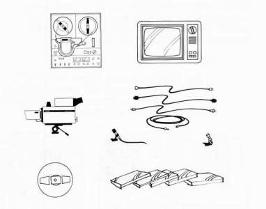
Recording with the VTR
Equipment Needed:
1 VTR
1 Monitor
1 Video camera and Lens 1 Microphone
1 Tripod for Camera
Plugs and Wires Needed: 1 AC CORD for VTR
1 8-Pin TV-Monitor connector
1 Camera cable, either 6-Pin or UHF cord 1 30 foot microphone extension cable
Accessories Needed:
1 take-up reel
Videotape
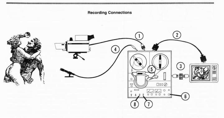
Video Recording Connections and Set Up Recording Procedure
Read the Instruction Manual first!
Step 1 Connect the camera to the VTR with a camera cord (UHF or 6-Pin).
Step 2 Connect the VTR to the monitor with the 8-Pin cable.
Step 3 Connect the AC power cables.
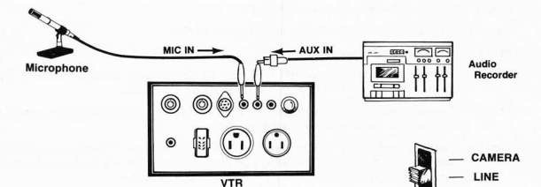
Step 4 Connect the microphone to the VTR.
Step 5 Thread the tape and set the tape counter to 000.
Step 6 Turn everything on.
Step 7 Set the input selector switch to CAMERA (6-Pin only types) or LINE if recording from a camera or a VTR or to TV if recording off-the-air.
Step 8 Select proper recording mode (for color VTR s only). Select COLOR mode if recording color or B&W mode if recording b&w.
Step 9 Depress the RECORD button until it locks into position. The red recording light will come on and the picture should appear on the TV monitor. Make your video and audio adjustments at this time. The VTR is now ready to record.
Step 10 To begin recording, hold down the RECORD button with one hand and turn the FUNCTION LEVER to the FORWARD or PLAY position with the other hand. The picture and sound are now being recorded simultaneously.
Step 11 Adjust the audio and video levels if operating with manual audio and video controls. Adjust the control knob so that the needle barely hits the red zone on peak sounds.
Step 12 At the end of the recording, place the FUNCTION LEVER in the STOP position. Rewind the tape and watch the playback.
Audio Dubbing
On nearly all recording VTR s, new sound can be added or DUBBED after the initial recording without erasing the picture. However, the original sound is erased on that portion of the recording where the new sound is added.
To Add New Sound
Step 1 Plug in the microphone to the M IC IN input or plug a tape recorder into the AUX IN input on the VTR. Only one audio input can be used at one time.
Step 2 Set the INPUT SELECTOR switch to CAMERA or LINE input.
Step 3 Play back the prerecorded tape, and when the proper scene appears, stop the VTR.
Step 4 Depress the AUDIO DUB button and simultaneously place the FUNCTION lever in the FORWARD or PLAY mode.
NOTE: If using the manual control for audio, be sure to match the level of the new sound with the preceding level. Use the meter to check the level of the preceding sound and then match the new sound to the same level.
Step 5 When the new sound recording is finished, turn the FUNCTION lever to the STOP position, rewind the tape, and play back the sequence. This procedure can be repeated as many times as desired.
Erasing the Tape
The simplest method for erasing a tape is to unplug all inputs to the VTR and run the machine in the RECORD mode. There is a more professional way to do this, however, and that is to RECORD BLACK or a solid dark blank which then appears on the monitor instead of the plain static or random noise which is generated from an unrecorded part of the tape. The neater blank or BLACK is created prior to the program and after it by either of two methods:
Method No. 1
Switch both audio and video recording controls to MANUAL CONTROL and turn both manual controls all the way down to the 0 level. Then place the VTR in the RECORD mode.
Method No. 2
Plug a camera into the VTR. Place a lens cap on the camera and turn the camera ON. Then place the audio control on MANUAL and turn it down to the 0 level. Now place the video control on AGC/AUTO or set the MANUAL control for the proper video level. Finally, place the VTR in the RECORD mode.
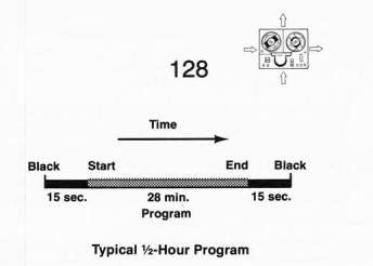
Method 2 is the best way of recording black because the sync is actually being recorded on the tape from the camera. The sync provides the VTR with something to lock-up to while recording. It's always a good idea to record 10 to 15 seconds of BLACK on both the beginning and the end of the program.
Fade-In, Fade-Out Procedure
Your program will look more professional if it fades in at the beginning and fades out at the end.
Step 1 Plug in the camera.
Step 2 Turn on the camera.
Step 3 Leave the lens iris fully closed or the lens cap on the camera.
Step 4 Place the VTR in RECORD mode for 10 to 15 seconds.
Step 5 Remove the lens cap quickly from the camera, or open the lens iris and immediately cue the action to begin.
Step 6 Complete taping the action.
Step 7 Replace the lens cap or close the lens iris at the end of the action.
Step 8 Allow the VTR to continue running in BLACK for 10 to 15 seconds.
NOTE: Do not fade out by turning the MANUAL VIDEO knob to "0" (zero) as the video sync pulses (control track) will be reduced to zero and the video image will become unstable.
Bulk Erasing
Sometimes it may be desirable to erase the entire tape at once. Bulk erasers can be purchased that erase a 60 minute tape in seconds.
SPECIALIZED VIDEO RECORDING SYSTEMS
T here are several kinds of low-to-moderate cost VTR s that offer specialized options that are most useful to program production.
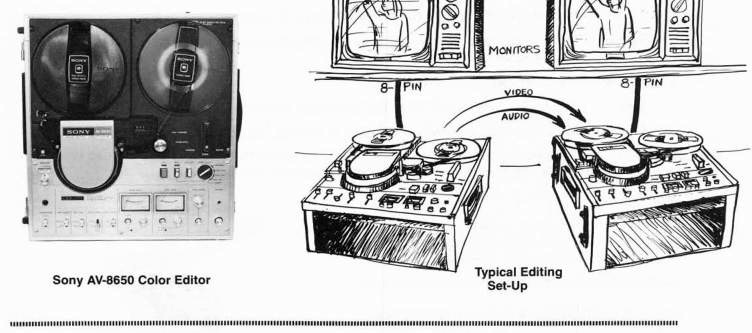
Editing VTRs
Videotape is edited by copying out or assembling the best segments from a series of master tapes onto a blank tape. This ASSEMBLY process requires a rerecording of the taped footage to be made on a second EDITOR VTR. Thus you need 2 VTRs for editing videotape—one to play back the master tapes and one to rerecord the newly edited tape. The playback machine can be any VTR on which the tapes will successfully play back, but the second VTR must be an EDITOR VTR which has special editing features.
Bulk Eraser
An electronic editing VTR must have a CAPSTAN SERVO mechanism which essentially enables the VTR to do 2 things at once-1) monitor the tape that is being played back, and 2) simultaneously reference or "LOCK UP" to the sync coming from the other VTR, so when the command to edit is given, the new material can be smoothly added to the previously edited sequence of material without producing a GLITCH or distortion at the edit point. All electronic editing VTRs must be capstan servo VTRs, otherwise they cannot perform smooth edits.
It's also very beneficial to use a capstan servo VTR as your playback VTR as well, because tapes will always be more stable (have better sync) when played or recorded on capstan servo VTRs. The more stable your tapes are the better your edits will be. So, use 2 capstan servo VTRs for the best editing results.
The other important feature of an editing VTR is its ability to edit video and audio information onto a tape in a variety of sequences. These editing modes are called ASSEMBLY and INSERT EDITING and refer to the sequential process of adding and changing scenes on an edit tape. A good editor VTR is able to edit video and audio tracks individually and/or simultaneously without delays, glitches or pops at the edit points.
The best editing reel-to-reel VTR for the price is the 1/2-inch EIAJ Sony AV-8650. The AV-8650 performs flawless editing 98% of the time with absolutely no audio abnormalities. The edit control switch on the AV-8650 permits any combination of assembly/insert mode—video/ audio editing that is possible on 1/2-inch tape. It's a superb machine; it's one of Sony's best designs; and it delivers high quality color especially in the high-density mode.
3/4-inch editors are numerous and include the Sony VO-2800, VO-2850, VO-2860, the JVC CR-8500 LU,and the Panasonic NV-9500. See Chapter 11—Videocassette Editing, p. 143.
Slow Motion VTRs
There is more to video slow motion than merely slowing down the tape. The scanning of the tape by the video heads must be altered, otherwise objectional frame lines will appear on the screen. Certain VTRs have eliminated this problem by using 4 video heads and a special scanning process which produces a clean, true slow motion at 1/6th normal speed. Popular true slow motion 1/2-inch VTRs include the Javelin X-400 ($2,000) and the Sanyo line of slow motion VTRs, such as the non-EIAJ Sanyo 1/2-inch portapak.
Slow Motion Video
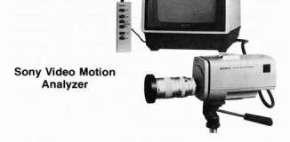
The practical use of video for slow motion has been inherently limited because of its slow scanning speed of only 30 frames per second. Anything that moved fast would therefore be blurred to the video camera. Sony, though, developed a combination video motion analyzer/ videostrobe system that effectively increases the speed of the video system. By using a unique b&w camera with a rotary shutter that shoots at a considerably higher speed than 30 frames per second, very fast action can be recorded without blur.
The system consists of the RSC-1010 b&w video camera and SVM-1010 video motion analyzer with built in b&w battery powered monitor with full-function remote control. The pictures from the camera are recorded on a special magnetic sheet located in the monitor unit. Up to 10 seconds of action can be recorded on the sheet and played back in real time (normal speed), in 1/7th or 1/15th slow motion speed, in forward or quick reverse, or the motion can be advanced, reversed and analyzed frame by frame, The whole system is battery operated, and the recorder and camera output can be connected to any VTR. A strobe input enables the camera to be synchronized with an external strobe lamp for greater versatility. A system such as this is ideal for industrial or sports
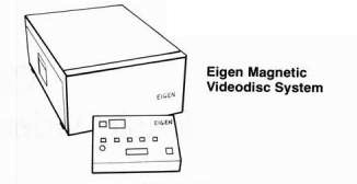
Slow Motion Videodiscs
T he videodisc is much better suited to producing special video playback effects. The MAGNETIC VIDEODISC process is utilized by broadcast TV networks for the instant replay of sports events. The video pictures are stored on a magnetic disc instead of magnetic tape and can be replayed at any speed or stopped on a single frame. T hese machines are very sophisticated and expensive.
A less expensive ($15,000) version of the Broadcast Videodisc System is manufactured by the EIGEN COMPANY, P.O. Box 1027, Grass Valley, CA 95945. The E igen color disc recorder records individual TV fields on single tracks, thereby reproducing perfect still images when played back. The tracks are recorded in a series of concentric circles on the magnetic disc.
Time Lapse VTRs
Another way to use a slow motion VTR is to record in the slow motion mode and then play the tape back at normal speed. The effect will be a picture of greatly accelerated motion—many times the normal speed. A good slow motion VTR is a very helpful tool for creating slick special effects, since these effects can be edited into the videotape production.
The Panasonic NV-8030 time lapse VTR provides continuous taping of up to 108 hours with a standard 60 minute roll of 1/2-inch tape. The NV-8030 has several selectable speed modes and can record only one single field at a time. This is called the "1-shot" mode. A built-in alarm and alarm memory permit rapid tape search for periods recorded during alarm conditions. This kind of VTR is normally used for surveillance applications but could also be used to produce some interesting production effects.
Summary
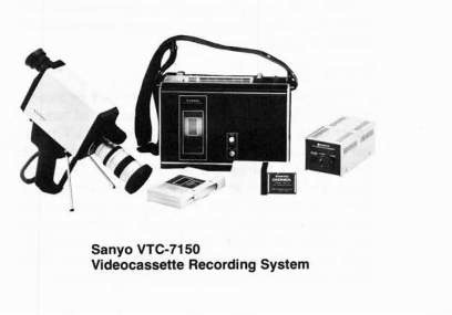
Since 1/2-inch EIAJ VTR s have been around and standardized for a while, they offer a great deal of flexibility for the lowest cost. For basic b&w production, surveillance, or "video work print" purposes, the 1/2-inch reel-to-reel can't be beat. For more sophisticated video production, particularly color work, the 3/4-inch videocassette systems are more appropriate, and the 1/2-inch videocassette systems are more practical for low-cost program distribution.
So, let's move on to some basic videocassette equipment and explore its operation and set-up.
motion studies.