Chapter 14
Maintenance, Troubleshooting, And
Minor Repairs
Like people, machines need love and care on a regular basis. If video equipment is kept in good health, the chance of a major breakdown and its associated expense will be minimized, and the equipment's life expectancy will be dramatically increased.
Since video cameras and TV monitors are nearly all solid state electronics, there's not much that can happen to them, unless they're dropped or a
camera tube is burned. Multiple tube color cameras may occasionally need tube registration and electrical focus adjustments. Tube registration should be left to someone who knows what they're doing, VTRs, on the other hand, contain many moving parts and points of contact where videotape deposits can clog vital functions and metal surfaces can wear and become dirty.
A HEALTH CARE PROGRAM FOR YOUR VTRS Cleaning the Recording Heads
The various video, control, and audio heads should be cleaned on a regular basis—every 8 to 1❑ hours of operation or so for a "quick clean" and a major clean at 20 or 30 operating hours. If a number of different people are regularly using the VTR, it should always be cleaned before
you use it.
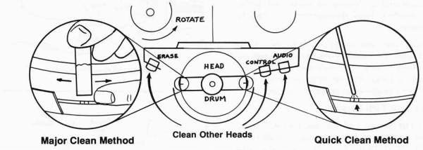
"QUICK CLEAN" Method—Reel-to-Reel VTRs:
Step 1 Make sure the power is turned OFF and the rotating heads are completely stopped. The VTR should make no noise whatsoever.
Step 2 Turn the function lever to REWIND or FF mode.
Step 3 Remove the tape reels from the machine and slightly turn either the supply-reel spindle or the take-up-reel spindle until the video head rotates into an accessible position.

Step 4 Thoroughly spray the first video head with the tape cleaner and then rotate the second video head into position and spray it also.
NOTE; VTR s with rotary erase heads will have 4 heads to spray.
Step 5 Spray the surface of head drum (tape path area), and erase audio, and control track heads as well.
Step 6 Turn the FUNCTION LEVER to STOP and wait a few minutes for the spray to dry on the head surfaces.
Step 7 You can now turn the VTR back on.
MAJOR CLEANING METHOD
Step 1 Turn the VTR OFF. No sound should be heard from the VTR.
Step 2 Place the FUNCTION LEVER in REWind or FF mode and remove the tape reels.
Step 3 Rotate the supply reel spindle slightly by hand so the video heads swing into an accessible position—one at a time. They are located 1800 apart.
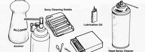
Step 4 Spray the tape cleaning swabs with tape head cleaner or immerse them in denatured alcohol and gently rub each video head in a back and forth manner—carefully!
Step 5 Find a good light source so you can see what you are doing and clean the tape guide path. Clean all the stationary tape guides and surfaces which the tape might come in contact with. You can rub fairly hard on the surfaces of the stationary record and erase heads without risking damage.
Step 6 (Optional) Gently and carefully wipe off the head drum surface with a cleaning cloth or a lens cleaning tissue.
Step 7 Place the VTR FUNCTION LEVER in the STOP mode.
CAUTION: NEVER move the head cleaner vertically against the video heads. NEVER touch the video heads with a hard object.
NEVER touch the video heads while they are in motion—The heads are brittle and will break easily.
Cleaning the Cabinet
When the VTR cabinet surfaces become dusty or dirty, clean them with the provided cleaning cloth or other fine quality cleaning cloth. Never use solvents such as thinner or benzine as they may cause damage. Always wipe the surface of the head drum and tape path before and after operating the VTR near or on the sea or in a location where acid or alkali gasses are used.

Demagnetizing the Heads
If the VTR is used constantly, the heads may become magnetized resulting in poor picture quality characterized by excessive noise and grain. Use the standard head demagnetizer to rectify the problems.
Place the head demagnetizer near each head (do not touch the head). Turn the demagnetizer ON and move it slowly away from the VTR and the recording head. Repeat this process 2 or 3 times for each head—both audio and video.
Removing Tape Path Deposits
After 10 to 20 hours of use, deposits will build up in the corners of the tape path guides and around the head drum. Spray cleaner evaporates too fast to really remove any heavy deposits. Use a cleaning swab or 0-tip and saturate it with cleaning alcohol to dissolve the tape deposits and residue. Unfortunately, the swab cannot get into the tiny corners of the tape guides. A long wooden toothpick is excellent for this purpose. Clean around the edges of the tape guides and especially the EDGES OF THE TAPE PATH around the video head drum. The buildup of deposits around the head drum can easily cause mistracking.
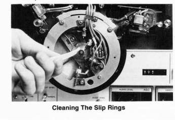
Cleaning the Slip Rings
All VTRs must have some means of transferring the picture information from the rotating video heads to the internal electronics of the machine. Most 1/2-inch VTR s use SLIP RINGS to accomplish this purpose. Occasionally, these slip rings must be cleaned, especially if the VTR is used in a dusty environment. Dirty slip rings will produce an effect in the picture playback much like tape dropout. The difference is that the black line of interference caused by a dirty slip ring will be constant and stay in one place in the picture, whereas the black line caused by a dropout will be only momentary.
Slip Ring Cleaning Procedure
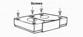
Step 1 Lift off the head drum protector by loosening the screws behind it.
Step 2 Carefully remove the 2 screws on the
top of the head drum cover.
Step 3 Remove the cover.
Step 4 Turn the VTR ON and place it in the STAND BY or RECORD mode with the video heads rotating.
Step 5 Saturate a swab or small piece of paper in alcohol and apply the swab firmly to the revolving slip rings or insert the edge of the paper into the slip ring recesses. Continue the process until the swab or the paper ceases to accumulate dirt.
NOTE: Certain better quality VTRs have no slip rings. Instead, they use a more precise method of transferring the video cal led a ROTARY T RANSFO RMER. The Rotary Transformer has no mechanical moving parts to create friction and wear, so it never needs cleaning.


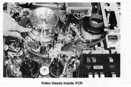
CLEANING THE VIDEOCASSETTE RECORDER
Since neither the head drum nor the videotape is exposed to manual handling, cleaning the videocassette recorder becomes less critical than with reel-to-reel VTR s. Nevertheless, occasionally the unit should be cleaned as tape deposits will eventually build up on the head drum surface and the tape path guides.
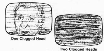
Clogged Heads
Like a reel-to-reel VTR, the VCR has the same kind of circular head drum, rotating video heads, audio and control track heads and tape path guides. Poor quality tape, old or heavily used tape, or damaged tape can completely clog the video heads. One clogged head will display an entire picture but one with every other line missing or black. If both heads are clogged, the monitor will display only black and gray "noise." Sometimes these symptoms wi II last only for a short time and soon clear up as the tape continues to play. At other times, a major cleaning will be necessary to restore the picture. Special cleaning cassettes are available for this purpose.
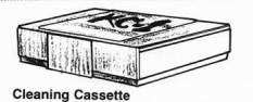
Procedure for Using the Cleaning Cassette
Step 1 Insert the cleaning cassette into the VCR.
Step 2 Reset the tape counter to 000.
Step 3 Press the FWD button and watch the tape counter.
Step 4 Press STOP when the counter reaches 010. This should correspond to 30 seconds.
Step 5 Remove the cleaning cassette,
NOTE: Do not rewind the cleaning cassette after each 30 second use; wait until it reaches the end of the tape. It can be rewound and used over many times, but after prolonged use it will require replacement.
CAUTION: Do not overuse the cleaning cassette as it uses abrasives and may decrease the life of the machine,
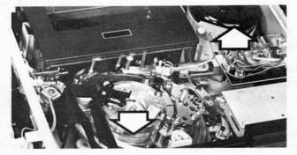
Manual Cleaning of Videocassette Unit and Removal of Cover— 3/4-Inch U-Matic
If the cleaning cassette will not restore the picture or if the tape is jammed inside the machine, it may be necessary to get inside the VCR. if you feel reluctant to do this, find a video repair shop or skilled video person. If, on the other hand, you want to tack le this yourself, proceed as fol lows:
Step 1 Make sure the VCR is turned OFF,
Step 2 Remove the screws from the back of the top cover. You will need a small screwdriver (Phillips with some, regular with others), or a METRIC Allen wrench for older Sony models.
Step 3 Carefully lift up the top cover, sliding it out HORIZONTALLY from the rear.
Step 4 Clean the heads and tape path guides just like you would do with a reel-to-reel VTR. See the first part of this chapter. Two features are unique to VCRs:
-
The entire video head assembly rotates with the heads. Merely turn the head assembly to locate the individual heads.
-
The control track and audio heads are hard to locate and clean. Follow the tape path to find the various heads and check for deposits on the tape path gu ides.
CAUTION: The tape guides are supposed to look crooked and bent—DO NOT try to straighten them out or you will destroy the tape threading mechanism and your tape!
Cassette Tape Repair Procedure— 3/4-Inch U-Matic
if the tape becomes damaged or you have to cut off a piece which got jammed in the machine, repair of the cassette tape is as follows:
Step 1 Place the cassette down flat on a table with the back side up.
Step 2 Take out the 5 screws that hold it together. Use a Phillips head screwdriver and be careful with the front guide assemble screws. Remember how the screws are supposed
to fit back in place,
Step 3 Remove the top cover of the cassette.
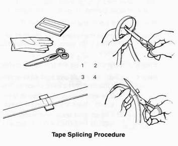
Step 4 Splice the remaining good tape together or onto the clear leader:
-
Cut off the bad tape and overlap the ends of the good tape together.
-
Cut the tape at a right angle.
-
Join the ends together.
-
Carefully apply the video splicing tape.
-
Trim the ends so no overlap exists.
NOTE: Use the video splicing tape only! Never use audio splicing tape!
Step 5 Rewind the tape carefully by hand back into the cassette, making sure the tape is threaded through the proper tape guides.
Step 6 Reassemble the metal tape guides, top cover and all the screws.

Head Cleaning Procedure-1/2-inch VCRs
1/2-inch VCRs can be cleaned just like the 3/4-inch VCRs and will need new belts, brakes and major adjustments every 1,000 to 1,500 hours.
Step 1 Make absolutely sure the VCR is turned OFF, and no whirring sounds are coming from the VCR.
Step 2 Remove the screws from the top cover of the machine using a narrow-tip phillips screwdriver while being careful not to damage the screw heads. Next, remove the TRACKING knob from the front of the machine. It should pull or pry off the shaft.
Step 3 Press the EJECT button to raise the cassette compartment and carefully remove the cover from the machine.
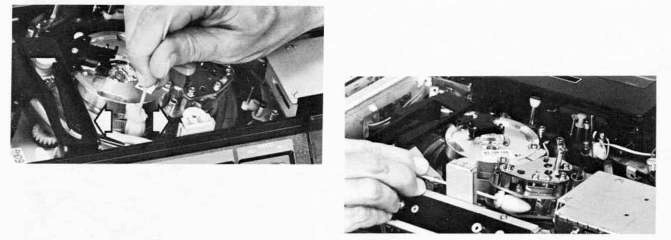
Step 4 Clean each of the two video heads by rotating them into position by turning the motor fan shroud. This will rotate the entire video head assembly into position.
Step 5 Spray a cleaning swab with the head cleaning solution. Very carefully clean each
head by using a back and forth HORIZONTAL motion only in the same plane as
the tape travels. DO NOT rub the video heads vertically as this may easily cause
severe head damage.
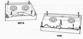
Step 6 Clean the video erase, audio and control track heads. On Betamax VCRs, these heads are located in the large assembly next to the circular head drum. VHS machines have the heads located on the tape path to the right and left of the head drum cylinder. Spray the swab with the head cleaner, and clean the heads and tape guides until all deposits have been removed.
Step 7 Replace the cover and all knobs on the VCR. Turn the machine on, and play a tape to confirm that everything is working ok. If it isn't, repeat steps 5 and 6.
3/4-Inch Cassette Tape Repair Procedure
Step 1 Use a narrow-tip phillips screwdriver to remove the screws that hold the cassette together.
Step 2 Carefully grasp the cassette and turn it
over so the label faces you.
Step 3 Depress the front panel release catch on the left side of the cassette, and open the tape protector panel.
Step 4 While holding the spring loaded tape protector panel open, carefully lift the top cover of the cassette off the body of the cassette.
Step 5 Splice the remaining good tape together or onto the leader using the method mentioned earlier for 3/4-inch tape.
NOTE: Use video splicing tape only. Never use audio splicing tape.
Step 6 Rewind the tape carefully by hand back into the cassette, making sure the tape is threaded through the proper tape guides.
Step 7 Reassemble the cassette, replace the
top cover and all the screws.
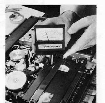
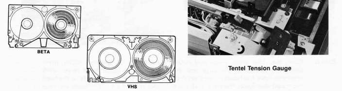
Maintaining Correct VTR Tension
Another important operating parameter in any VTR or VCR is its tape tension (skew). With use, the tension will change as belts, rollers and wheels wear, and in extreme cases, incorrect tape tension will cause flagging at the top of the screen during playback. Tension errors will of course be recorded into tapes recorded on a malfunctioning machine. To check your machine's tension, a company called TENTEL of 50 Curtner Ave., Campbell, CA 90058, makes a tension gauge called a TENTELOMETER for 3/4-inch and inch VCRs. The cost of the unit is $195, and clear and concise instructions for measuring your machine's tension are included in the kit. This device would be very helpful to heavy VCR users who are concerned about tape quality control.

Threading Mechanism Malfunctions
If a VCR experiences extremely heavy use, the roller that drives the threading chassis on older VCRs may become worn out, causing the machine to stall halfway through threading. Replacement of this roller is tricky, and it should be referred to a competent video repair person. Another serious problem results if the automatic shut-off and de-threading mechanism fails at the end of the tape. The tape will stop and remain locked around the video head causing friction against the video heads which soon destroys them. If you notice that the tape stops at the end of the reel and the machine does not de-thread immediately, shut down the machine at once and take it to a competent repair facility. DO NOT attempt to remove the cassette.
TROUBLESHOOTING
Psyching Out the Machine
Unlike people, machines can't tell you where it hurts. They just suddenly or intermittingly cease to function. When this happens, PATIENCE NOT PANIC is the approach to take.
Human Error
Most problems are due to simple human error; probably 80% to 90% of all malfunctions stem from tape misthreading,cables plugged into wrong inputs or outputs, or switches placed in improper modes. CHECK THESE THINGS OUT FIRST!
Mechanical and Electronic Malfunctions
The other 8% to 10% of machine problems are due to mechanical failures such as broken plugs or wires, dirty heads, broken switches, etc., which a good mechanically inclined person can fix personally. The remaining 2% or so are due to electron is problems such as component failure, which take a competent VTR service technician and the proper test equipment to fix.
Cosmic Interference and Mental Attitude
Then every once in awhile, strange things happen; usually the "come-and-go" type where your system will suffer severe picture distortion, horrible color quality, or loss of audio minutes before or during the big production. The VTR operator and director often experience waves of nausea and acute mental hallucinations usually accompanied by recurring questions such as "Why me?" or "What did I do to deserve this?"
Assuming everything is properly connected, there is another cause to consider. Even so-called
inanimate matter such as electronic circuits and pieces of metal and plastic are all made up of atoms and molecules that must bind together in a certain absolute pattern. A kind of INTERNAL INTELLIGENCE and energy is necessary to maintain this pattern. A VTR has a great variety of moving parts and must maintain a vast multitude of precise electronic levels and critical tolerances that must all function together perfectly 100% of the time. The slightest deviation in one component's performance will often adversely affect all the rest.
The internal intelligence of VTR s and cameras will definitely respond to highly negative or positive emotional fields generated by people. Like organic matter such as plants, animals or people, a video system will respond well to those operators who approach it with care and love. An overly frustrated or negative person will pass those personal frustrations onto the equipment and


"strange" failures will inevitably result. This is why equipment "works" for certain people and "doesn't work" for others. It happens every time. Thus COSMIC INTERFERENCE may be your problem rather than the machine's. If you're convinced the equipment will break down on the job, it definitely will. Be prepared for all contingencies, but approach your production with a positive mental attitude.
General Principles of Troubleshooting
When things don't work very well or refuse to function at all, try these general principles of troubleshooting in order. Remember—BE PATIENT, DON'T PANIC, your problem is probably due to human error.
-
Start from the beginning again. Unplug everything and plug it in again. You may have your VIDEO INS and VIDEO OUTS mixed up or a plug may not be plugged in all the way.
-
Rethread the videotape. Check the threading diagram on the cover of the VTR.
-
Start with what you know works. Substitute a second cable, VTR, camera, monitor, or microphone that you know works—substitute one at a time and see what happens.
-
Isolate the Malfunction. Through substitution of a component, you should be able to isolate the problem area. If nothing works, check your main power source and try other batteries and/ or AC plugs. Check for power switches that are turned off, blown circuit breakers or fuses.
|
|
|
| ||
|
Troubleshooting Reference Chart Symptom Probable Cause Solution | ||||
|
|
Unit does not turn ON or |
dead battery with portable VTR |
recharge or replace battery or use AC power |
|
|
|
|
VTR is not plugged in or switch not turned ON |
plug in and turn ON |
|
|
|
|
auto shut-off mechanism is jammed |
rethread tape and fix mechanism |
|
|
|
|
fuse circuit breaker in AC |
replace fuse or reset circuit |
|
|
|
|
system blown |
breaker |
|
|
|
|
fuse in VTR blown |
replace fuse |
|
|
|
No picture on camera |
camera cable problem |
check cables or use substitute |
|
|
|
|
cable not plugged in |
cable |
|
|
|
|
camera or VTR is not turned |
turn camera and VTR ON |
|
|
|
|
ON |
|
|
|
|
|
batteries dead |
replace batteries or use AC power |
|
|
|
|
beam or target control on camera improperly adjusted |
reset beam and target |
|
|
|
No picture on camera |
VTR monitor connection is |
substitute new cable |
|
|
|
viewfinder or monitor when |
faulty |
|
|
|
|
VTR is in E to E mode |
monitor mode switch in TV |
switch to VTR or LINE mode |
|
|
|
(VTR is ON) |
mode |
|
|
|
|
|
wrong cable connections |
check cables |
|
|
|
|
faulty plugs or connectors |
check or substitute other plugs or connectors |
|
|
|
|
source selector switch on VTR |
source or input selector switch |
|
|
|
|
is not in the proper mode |
should be on LINE on most |
|
|
|
|
|
VTRs and CAMERA for some try both positions |
|
|
|
|
video level control |
switch video level control to |
|
|
|
|
turned OFF on VTR |
AGC |
|
|
|
no picture or loss of sync |
I NT/E XT sync switch on camera in wrong mode |
try INT sync |
|
|
| ||||

|
|
| ||
|
Symptom |
Probable Cause |
Solution | |
|
|
Interference in picture during |
COLOR/BW switch on VTR |
select correct mode |
|
|
camera monitoring |
in wrong mode |
|
|
|
|
faulty cable connection |
replace cable |
|
|
|
AC cables too close to video cables |
move cables |
|
|
|
AC power cables not grounded |
use 3-prong plugs and connections only; ground 3 to 2 prong adaptor or reverse polarity of 2-prong plug |
|
|
|
|
(reverse the prongs in the socket) |
|
|
spots or black squiggly |
dirt on camera tube or burned |
clean lens and tube faceplate or' |
|
|
lines in picture |
vidicon |
replace tube if severely burned. |
|
|
distortion or interference |
dirty heads |
clean heads |
|
|
during picture playback |
tape improperly threaded |
rethread tape |
|
|
|
dirt in tape path |
clean tape path |
|
|
|
dirty slip rings |
clean slip rings |
|
|
|
COLOR/B&W switch on VTR in wrong mode |
select correct mode |
|
|
|
high-density tape mode switch in wrong position (AV-8650 |
try other mode |
|
|
|
Sony and NV-3160 Panasonic) |
|
|
|
|
Source or Input selector switch |
switch to LINE or CAMERA |
|
|
|
on editing VTRs with capstan |
mode or push SYNC DEFEAT |
|
|
|
servo is in TV mode during playback |
switch during playback |
|
|
|
tracking poorly |
adjust TRACKING control |
|
|
|
tape faulty or old—has too many dropouts |
replace tape |
|
|
|
damaged video heads or |
replace heads—take to VTR |
|
|
|
control track heads |
service co. |
|
|
|
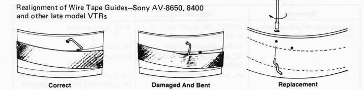
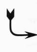
wire tape guides on certain |
realign or replace |
|
|
|
Sony VTRs bent |
|
|
distorted or loss of sound |
faulty microphone connection |
check or replace cable | |
|
| |||
|
|
|
bad or reversed battery in condenser microphone |
replace or reverse battery |
|
|
|
audio controls on VTR turned |
turn on audio control/limiter or |
|
|
|
OFF |
AGC |
|
|
|
wrong connection |
microphone should be plugged into MIC IN or mixer should be plugged into LINE IN on VTR |
|
|
persons receive shock when |
wrong polarity |
reverse AC connections of mixer |
|
|
touching microphones |
|
or VTR system |
|
|
Radio noise in audio |
radio station nearby |
shield audio and video compon- ents with copper screen or alumin- um foil; uncoil audio cables or move audio cables away from AC cables |
|
|
NOTE: If all else fails, reread the instruction manual and try again a few days later. If your second | ||
|
attempt doesn't produce results, take the equipment to a good repair facility. | |||

To fix—turn VTR OFF and use needle nosed pliers to bend guide out of tape path, Replace guide by removing video head cover, and use a jeweler's screwdriver to remove and replace the guide assembly.
Tape Winding and Storage Problems
Sometimes a VCR will shut off and de-thread in the middle of a tape playback for no apparent reason. This is usually due to excess slack in the tape created during storage of the cassette. The automatic sensing mechanism in the VCR will sense the excess slack and shut down the machine automatically. Because the tape reels overlap on a 3/4-inch cassette, the uneven weight of the tape on the reels causes it to produce excess slack, stretching and other problems—usually during storage. Cassette tapes should always be rewound after use. It's also helpful to fast forward and rewind the tape several times before playing or recording. This will eliminate slack.
No Picture or Recording on TV Set or Monitor in RECORD Mode
Check the bottom of the cassette for the red recording lock-out button. The button must be in place before the VCR will go into the RECORD mode. On JVC machines, make sure the switch on the back panel of the VCR is in the VIDEO IN/ AUDIO position instead of the TV mode. Also on JVCs, make sure the ANTenna SE LECTor switch on the top of the VCR is in the VCR position.
Importance of a Regular Maintenance System
HORACE'S LAW OF VIDEO VENGEANCE:
"Equipment breakdown and repair expense increase directly with the number of different people who use the equipment."
Individuals who own their own video equipment and regularly maintain it can go for years without any major repair. Large groups, particularly students that use equipment, are always complaining about how nothing ever works. Several key persons should be designated to clean and maintain the equipment on a regular basis in a group use situation. Some discretion should be used when loaning out VTR equipment to untrained persons.
Special Videocassette Recorder Problems
Machine Eats Tape—Occasionally the tape guide will get off the track and wind the tape around the capstan roller, Usually the machine will then shut down. Make su re the VCR is turned OFF, Proceed to remove the VCR top cover, and very carefully try to gently remove the miles of tape that have filled the interior of your machine. You may have to cut the tape with scissors as it is now useless anyway. Once the crinkled tape is extracted, throw it away. You may also have to clean the machine afterwards.
If a certain VCR continually eats the tape, try another brand of cassette tape. If it eats that one too, try the "bad" cassette on another similar (same manufacturer) machine, If the tape works fine on the other VCR, the problem is your machine. If several similar VCRs all eat the tape, the chances are that this particular cassette tape has some bad spots in it or is defective. Consider switching to another brand tape. If you still have problems, consider switching to another profession or job.