SILVER-MIRRORING EDGE PATTERNS: DIFFUSION-REACTION MODELS FOR THE FORMATION OF SILVER MIRRORING ON SILVER GELATIN GLASS PLATESGIOVANNA DI PIETRO, & FRANK LIGTERINK
4 EXPERIMENTAL PARTTo verify the diffusion and reaction models presented above, two sets of experiments were performed. In the first set of experiments, a microscopic focusing technique was used to measure the curvatures of historical plates in order to determine local distances between adjacent plates. The correlation of local plate distance with local width of historically formed silver-mirroring edge patterns was checked against the theory. In a second set of experiments, the formation of silver mirroring was artificially reproduced on both single and stacked plates by exposure to a mixture of reactive gases in an incubation chamber. The resulting silver-mirroring edge patterns were compared against the theoretical predictions. 4.1 DETERMINATION OF PLATE DISTANCES AND EDGE PATTERN EXTENSION IN AN UNALTERED STACKThe present study is based on the survey of the Cueni Study Collection, a collection of about 150 glass plate negatives by the Swiss painter and amateur photographer Adolf Cueni, active in the Basel region in the years 1910–20. The plates, of no commercial value, were donated in the early 1990s by the Cueni family to the Laboratory of Scientific Photography of the University of Basel, in their original cardboard boxes, and have never been archived. The majority of
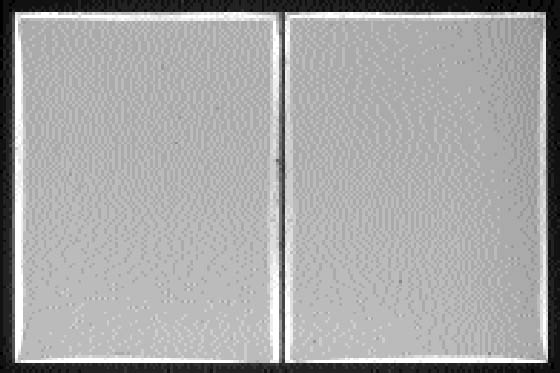
Obviously, it is not possible to check this relation unless the positions of the individual plates have not been altered since the development of the silver-mirroring edge pattern. Unfortunately, this is often not the case because historical plates have usually been manipulated a number of times in the course of their history. However, we were able to locate a number of plates showing silver mirroring that had never been moved. We found a number of nonprocessed and never-used glass plates still wrapped in the original black paper. Every wrapping paper contained the customary three pairs of glass plates. Within every pair, the emulsion sides were placed in contact. Not only did the plates show silver-mirroring degradation, but the pattern of silver mirroring on the two plates of a pair was exactly the same (fig. 9). To verify the expected relation between the local distance between two plates and the local width of the silver-mirroring edge pattern, it was decided to determine the variation in local distance between the plates. The distance between the two plates of a pair was measured by independently recording the shape of the two plates and recalculating the position in which they lay one on the other. The difference between the coordinates of the plates in this position gave the distance between the plates. Results of the interpolated distance measurements were then compared with photographs of the silver-mirroring edge patterns.
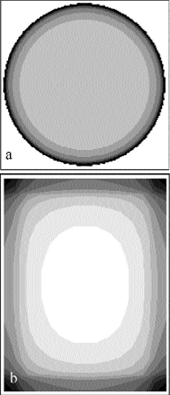
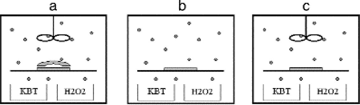
The shape of the plates was measured with a microscopic technique. The principle of the technique is based on the fact that the distance between the objective lens and the focal plane, the so-called focal distance, is a fixed characteristic of the objective lens. If the sample under observation is not flat, when the observation point is displaced on the sample the whole objective has to be moved up or down to get a focused image. By recording the coordinates (x, y) of the observation point and the coordinate z of the objective position, a map of the macroscopic shape of the sample is obtained. We used a confocal scanning laser microscope (CSLM) named Odyssey XL, produced by Noran Instruments. The CSLM is a system composed of an inverted light microscope (Axiovert 135 TV, Zeiss), a laser source (Omnichrome), a video-scanning module (Noran Instruments), and a host computer (Indy, Silicon Graphics). The images collected in the microscope are displayed, through the video-scanning module, directly on the computer monitor. The computer controls the microscope through a software interface (Intervision). We operated the microscope in the reflection mode with a laser wavelength of 568.2 nm with an objective (Pan Neofluar, Zeiss) providing a 40x magnification. The z position of the objective is automatically moved in fixed steps by the computer. The position of the observation point can be changed in the (x, y) plane by fixing the sample in the sample holder, which is connected to scales manually movable with micrometer screws. The standard sample holders do not allow for the fitting of a 9 � 12 cm plate. The plate was therefore positioned directly on the stage of the microscope and carefully attached with self-adhesive tape to the scales. We mapped the plate surface by recording the objective z coordinate on the points of a regular grid of 1 cm spacing, covering the whole plate. The error in determining the z position of the grid points is given by the distribution of the silver grains in the emulsion. It is on the order of 10 μm. The error in determining the (x, y) position is � 0.5 mm. Because of the limited availability of the confocal scanning laser microscope, with this technique we analyzed the shape of six plates. The shape of other silver gelatin glass plates was qualitatively evaluated with a simpler method. A highly flat metal blade was laid on the plate and illuminated from behind. The distribution of the light penetrating between the blade and the plate gave information on the plate shape. 4.2 INCUBATION CHAMBER EXPERIMENTSTo artificially create silver mirroring on new photographic plates, an incubation chamber was used to expose new processed silver gelatin glass negatives to the vapors of hydrogen peroxide (H2O2) and hydrogen sulfide (H2S) at 80% RH. This procedure was modified from the standard hydrogen peroxide test (ISO 2000). The incubation chamber is a 30 � 40 � 40 cm Plexiglas box covered with a lid fitted with a fan. The chamber hosts a sample holder of variable height and some trays for the evaporating solutions. Two trays are filled with a saturated solution of potassium chloride (KCl) to keep the RH at 80%. A third tray contains 10 ml of a 10% water solution of hydrogen peroxide. A fourth tray contains a 1:1 dilution in water of Kodak brown toner, a polysulfide toner releasing hydrogen sulfide. The glass negatives used are of the Agfa Avipan 100 type, of the dimensions 9 � 12 cm, and are uniformly exposed and processed in a standard way. The final plate density measured in T mode with a densitometer (X-Rite) is about 1.6. The plates are left in the incubation box for at least 24 hours at room temperature. From time to time, the hydrogen peroxide solution and the Kodak brown toner trays are recharged. The incubation chamber was used to perform three different exposure experiments. In the first experiment, a stack consisting of two plates was exposed in the chamber (fig. 10a). The horizontally orientated stack consisted of one historical glass plate whose shape had been previously measured with the microscopic method presented in section 4.1, on top of a flat, new, freshly processed Agfa Avipan 100 glass negative. In the second and third experiments, single plates were exposed in the chamber, without (fig. 10b) and with (fig. 10c) ventilation respectively. After exposure, the resulting silver-mirroring edge patterns
|