SEISMIC STABILIZATION OF HISTORIC ADOBE STRUCTURESWILLIAM S. GINELL, & E. LEROY TOLLES
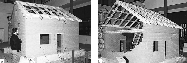
7 7. SHAKING TABLE TESTS ON 1:2 SCALE MODELSOne factor that could not be assessed in the small model tests was the effect of gravity on the behavior of massive, cracked, adobe block sections. Energy dissipation by friction between the moving blocks is dependent on the mass of the blocks, a factor that cannot be simulated accurately using normal density adobe in scale models. Testing of full-scale models would be prohibitively costly, and only one facility in the world (in Japan) has the capability of performing a full-scale test. Accordingly, half-scale (1:2) models, one retrofitted and the other not, were constructed and tested. These tests were performed at the 5 m square shaking table facility at the Institute of Earthquake Engineering and Engineering Seismology (IZIIS) of the University “SS Cyril and Methodius” in Skopje, Republic of Macedonia. The models constructed were of the same tapanco design as those of the 1:5 scale models 8 and 9 tested previously. Adobe materials strength tests and tests of assembled adobe wall segments were performed to try to match the properties of the California adobe used on the smaller models. However, the strength properties of the Skopje adobe proved to be lower, but it was probably more representative of the typical adobe, especially historic adobe, that is found throughout the world. The difference in strength affects only the initiation of cracks and should have had little effect on the postelastic dynamic behavior of the walls. The model dimensions were 3.7 by 3.7 m square by 3 m high with an SL = 7.4 (fig. 8). Instrumentation was installed for measuring both wall displacements at various locations and stresses in the walls and straps during the tests. Wall motions and crack damage were monitored by video and still photography in the same way as in the small model tests.
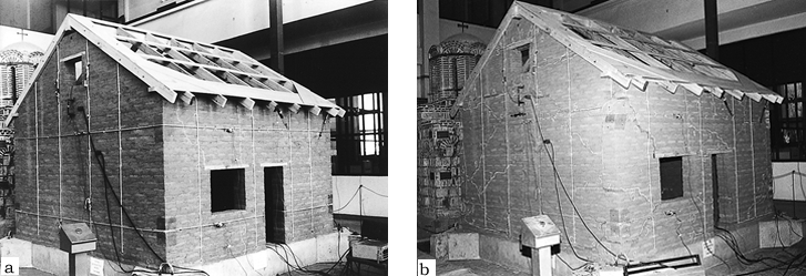
The retrofitting measures consisted of the following:
The west and the south walls were retrofitted with four vertical center core rods placed at regular intervals. During the construction, cavities 3 cm in diameter were formed in these walls using plastic tubes. After completion of the model, ribbed steel rods, 14 mm in diameter, were placed in these cavities, and the space around them was filled with an epoxy-adobe grout. The retrofitting measures for the east and the north walls were vertical nylon straps placed at regular intervals. Four vertical straps were used on both sides of the walls. The straps went over the tops of the walls and through drilled holes at the base of the wall. Small diameter straps were used for cross ties between these straps. Two horizontal straps were placed on each of the four walls. The upper horizontal strap was located at the attic floor line and was attached to the floor system. The lower horizontal strap was located just below the bottom of the window on both sides of each wall section. Partial wood diaphragms were added to the attic floor and roof, and wood blockings were inserted between the floor joists, which were anchored to the walls. The adobe parts of the model were cured for 80 days, and retrofitting was installed just prior to the shaking table tests. The first crack in the unretrofitted adobe structure occurred during the test at an acceleration level of 0.17 g and input displacement of 5.8 cm, and, owing to the loss of structural integrity, separation of the out-of-plane walls occurred. The level at which the elastic, first cracking, behavior of unretrofitted adobe building walls occurs is not usually significant because the walls of most historic buildings could already have some crack damage from water, earthquakes, or foundation settlement. During subsequent tests, many additional cracks appeared in all walls, and after the final dynamic test, the model was heavily damaged. Development of almost vertical and horizontal cracks was evident in the out-of-plane walls. After the final test the model suffered large nonlinear damage that resulted in the collapse of the east gable end wall (see fig. 8). The first crack in the retrofitted model structure occurred during the test at an acceleration level of 0.23 g and input displacement of 7.6 cm. Out-of-plane instability did not occur until the base motion (peak-to-peak) reached 75% or more of the thickness of the walls. Instability occurred at the start of test level VIII but might have occurred during test level VII if not for the stabilizing effects of the roof system. The maximum displacement of test level VII was 19 cm, and the peak-to-peak displacement was about 30 cm. The thickness of the walls was 41 cm, all in the prototype domain. During the subsequent tests, many cracks appeared in the east and north walls that were retrofitted using vertical and horizontal nylon straps. On the west and south walls that were retrofitted using vertical center core rods, fewer cracks were found. The failure mechanism in the final stage is the occurrence and development of diagonal cracks in the in-plane walls due to shear effects and large nonlinear damage in the out-of plane walls. After the final dynamic test, the east gable end wall of the model was heavily damaged, but none of the walls collapsed (fig. 9). In these tests, the gable end wall of the unretrofitted model collapsed at about the same level of shaking intensity as the smaller scale models. The crack patterns, too, were very similar. In the retrofitted model, the nylon straps and, especially, the center core rods proved very effective in preventing collapse.
|