SEISMIC STABILIZATION OF HISTORIC ADOBE STRUCTURESWILLIAM S. GINELL, & E. LEROY TOLLES
6 6. SHAKING TABLE TEST RESULTS ON 1:5 SCALE MODELSThe principal end results of the tests are summarized in table 3. Typically, cracks were initiated in the adobe walls during test levels III or IV at shaking table acceleration values of 0.23 g and 0.28 g, respectively. Cracks continued to develop during test levels V and VI, after which the principal cracked block sections had been defined and their location then determined the nature of seismic performance of the model during the succeeding tests (test levels VII and above).
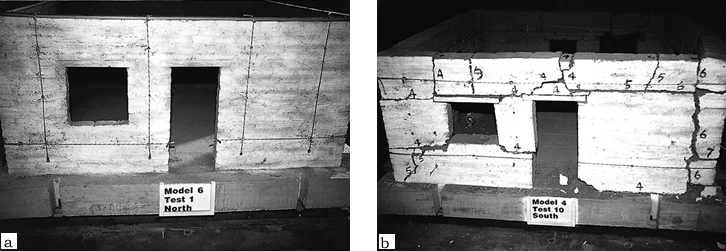
Unretrofitted models collapsed during test levels V or VI (see fig. 3). These test levels had an acceleration value of 0.32 to 0.40 g, and, more important, the peak displacements were approximately 16.5 to 24.8 cm in the prototype domain. In the prototype domain, thin walls (SL=11) were approximately 36 cm thick, moderate walls (SL=7.5) were 53 cm thick, and thick walls (SL=5) were 79 cm thick. Very high accelerations will not destabilize adobe walls if the frequency is high and the displacements are small. If the displacements are small, the base input may have large accelerations, but without large displacements, it is nearly impossible to destabilize the thick walls that are typical of many historic adobe buildings. Lightly retrofitted models were able to withstand somewhat higher test levels (fig. 6). Thin walls, with a bond beam and local ties, collapsed out-of-plane during test level VIII but the in-plane wall, with the same retrofit system, did not collapse until test level IX. The thick walls with horizontal straps remained standing through test level � while the moderate walls, with the same retrofit system, collapsed during test level X. Other models, with retrofit systems more complete than the lightly retrofitted models, showed greater resilience to extended, strong table motions. The addition of either vertical straps or center core rods greatly improved overall structural performance at the higher test levels, but the walls with center core rods sustained less damage through the test sequence than the walls with vertical straps only. Walls with horizontal and vertical retrofit measures continued to behave well through repetitions of test level X, and there were no indications of imminent collapse.
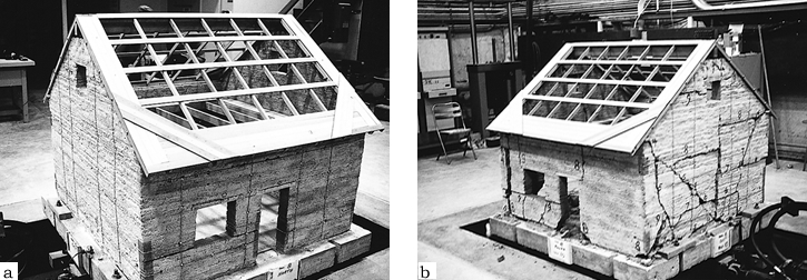
The results of the retrofitted tapanco model tests demonstrated the dramatic improvement in stability afforded by the wall retrofits and the continuity-assuring roof-to-wall attachments. Especially significant were the stability and damage control improvements that were provided by the thin center core rods (fig. 7).
|
|||||||||||||||||||||||||||||||||||||||||||||||||||||||||||||||||||||||||||||||||||||||||||||||||||||||||||||||||||||||||||||||||||||||||||||||||||||||||||||||||||||