THE CARE AND CONSERVATION OF GLASS CHANDELIERSJULIE A. REILLY, & MARTIN MORTIMER
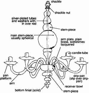
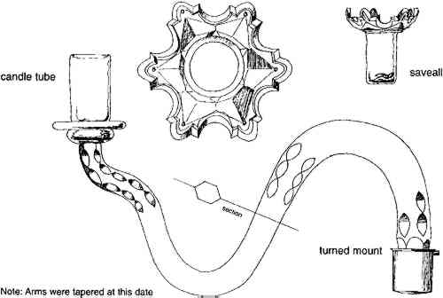
2 THE GLASS CHANDELIERLittle of a practical nature has been published on the subject of glass chandeliers (Davison 1988). Indeed, there is little written that accurately describes the evolution of the glass chandelier (Mortimer 1987). There is so little in print about the glass chandelier that this article and a detailed book currently in preparation by Mortimer will add significantly to the body of available information in print. From the mid-17th century onward it was fashionable to embellish the metal framework of lighting fittings with glass or rock-crystal ornaments in the form of faceted beads, shaped pendants, and other styles. However, it was not until glassmakers first risked load-bearing glass arms that the true glass chandelier was born. This The following discussion focuses on the generic structure for glass chandeliers, from their inception around 1720 until the end of the 18th century. There were, of course, continued improvements and changes as time passed, but the general assemblage remained fairly consistent. Figure 1 is a basic diagram of a glass chandelier, labeled with the terms proper for an early glass chandelier. A detailed glossary of terms can be found at the end of this article. Some terminology may vary from country to country or as design elements are developed and employed.
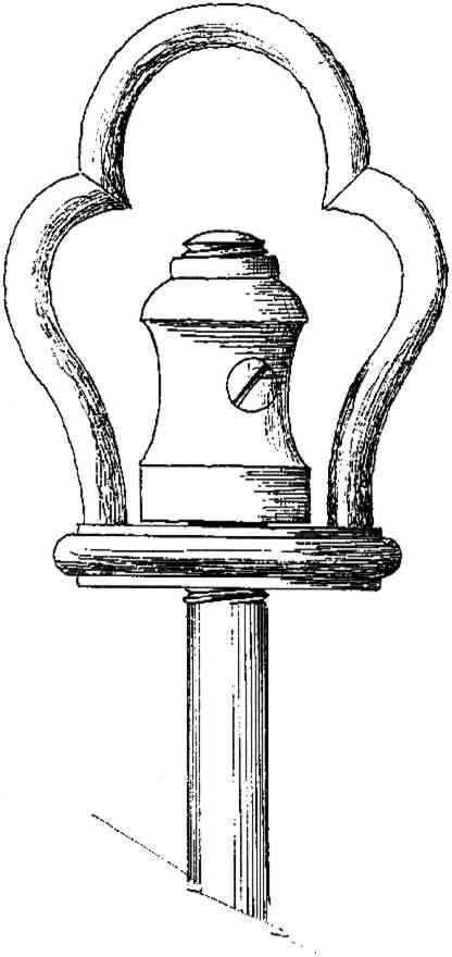
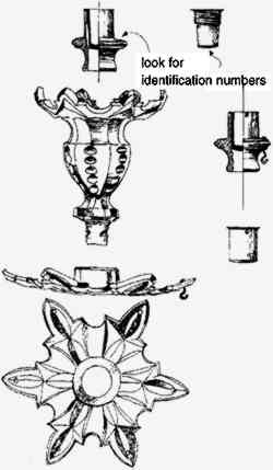
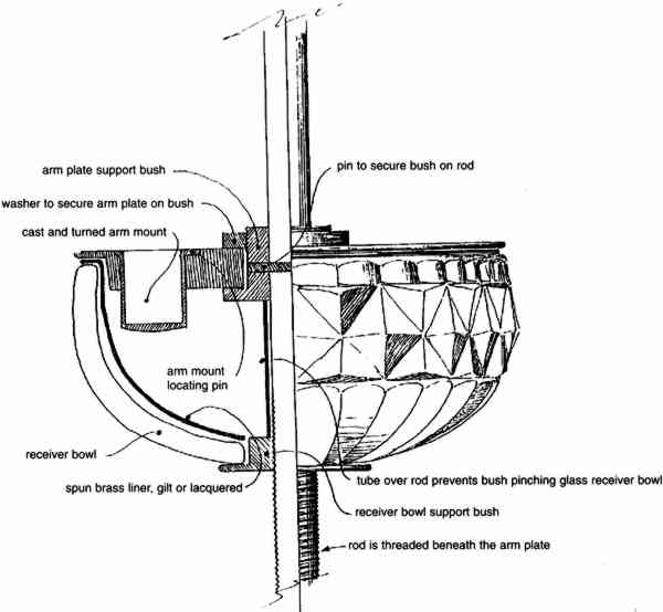
The elements found on the central stem of a chandelier, the stem-pieces, consisted of shaped glass forms arranged above and below a large central piece that was almost exclusively spherical (see fig. 1). The stem-pieces were supported on a metal rod that was, in earlier times, threaded along its entire length. One or two metal washers or bushings with conforming threads were positioned along the rod to take the weight of major stem-pieces and prevent their pressing too heavily on the stem-pieces below. A circular metal plate called the arm plate or receiving plate provided a console from which the arms emerged, each fitted with a cast square or turned round mount that fit into a unique matching hole in the arm plate. Corresponding mounts and holes were marked with pairs of matching letters or numbers to relate each mount to a specific hole. To hide the mechanical attachments on the underside of the arm plate, a glass receiver bowl was provided. The bowl was sometimes fitted with a spun metal liner or may have been gilded or silvered on the interior to further hide the mechanical fittings. The chandelier usually hung from a decorative suspension shackle, which was free to rotate 360�. The shackle was held on the support rod with a turned nut, which screwed onto the top of the metal rod and was prevented from unscrewing by a stop-screw inserted through the nut into the rod itself (fig. 2). The chandelier stem terminated with a glass finial, sometimes in
2.1 CANDLE RECEPTACLES AND ARMSThe first glass chandelier arms incorporated an integral drip-pan and candle-tube or nozzle. These elements were soon found to be impractical because a low-burning candle could crack the tube and perhaps even the pan. It would then make it necessary to replace the entire arm assembly, which would be difficult to match completely to the original. Thus, a detachable drip-pan came into use in 1730–35 and was made to slip over the integral candle-tube and rest on a glass platform provided for it (fig. 4). This construction continued until ca. 1780.
Meanwhile, continuing problems with lowburning candles cracking tubes resulted in the introduction of separate glass sconces or nozzles, also known as savealls, around 1760. These small, cup-shaped units had a built-in candle-tube that could be inserted into the existing tube affixed to an arm. The candle was placed in
By 1780, however, following the neoclassical revolution in taste, completely detachable candle nozzles evolved (fig. 6). These nozzles were vase-shaped, with the upper border cut to an elaborate profile known as the Vandyck border. The name derived from the shaped borders of lace collars worn by many of the artist's sitters. The arm terminated in a turned metal female fitting with a surrounding platform for the drip-pan. The drip-pan center hole was now much smaller since it no longer had to pass over a tube of sufficient diameter to hold a candle. Into the terminal female socket was screwed, or socketed, a conforming mount onto which the candle nozzle was affixed.
2.2 ATTACHMENT OF THE ARMSThe method of securing the arms to the arm plate, discussed briefly above, underwent only one change in the 18th century. Before 1750, the mounts were square and required much hand-fitting. Later, turned round mounts were used. These mounts could be cast and finished on a lathe, as could their sockets in the arm plate, and then installed in the arm plate and on the ends of the arms. Turned mounts also had a further advantage in allowing the glass arms to swing slightly side to side if touched by a ladder
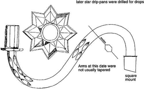
2.3 DECORATIONThe first chandeliers were plain. The stem-pieces were cut, often in flat planes. Occasionally they were molded, perhaps in a diamond mesh pattern. Arms were initially plain, but from about 1740 onward they were cut. The early cut arms appear to have been cut flat on each side, with long slices removed from the four resulting angled corners. Later, the arms were cut six-sided and then decorated with slices removed, as before. As the 18th century progressed, the slices |