Refractive Index
Foundation for Advancement in Conservation

© 2008
Introduction
Conservators need to understand the principles of the refractive index of materials when doing restorations. The physics for this subject is reasonably complex. I am going to make some simplifications to several of the concepts involved.
Those of you who really want to do the math should read through the article on refractive index on Wikipedia.
Contents
This tutorial is divided into the following sections:
Please complete each section in order, as the information builds on that covered in previous sections. You can return to any section later.
Press Ctrl+Shift+F to search.
Refractive Index Learning Objectives
After completing this section, you will be able to:
What Is Refractive Index?
The refractive index is all about the apparent changes that we see in the speed of light when it travels through a different medium such as water.
The physicests Essen and Gordon-Smith confirmed that the speed of light in a vacuum was 300,000,000 meters per second (give or take a few thousand meters).
Conservators would need to use the refractive index of an adhesive if they were repairing a transparent material such as glass.
Light Waves
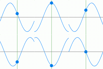
All energy (including light) travels in waves. The wavelength is measured from the top of one wave to the top of the next. The amplitude is the height of the wave.
Electromagnetic Spectrum

⟵ High energy end
We perceive only a very small part of the total electromagnetic spectrum as light and color.
The shorter the wavelength, the higher the energy.
⟵ Low energy end
Mathematical Definition
The refractive index \(n\) of any material is calculated from light passing from air into the denser medium.
\(n = \frac{c}{v}\)
\(c = \text{Speed of light in a vacuum}\)
\(v = \text{Speed of light in the denser medium}\)
The light travels more slowly through the denser medium because of interactions between its energy and the electron clouds. The light travels at the same wavelength in both the air and the denser medium but the frequency is slower in the dense medium.
Units of Measurement of Frequency
The frequency of light is measured in Hertz (Hz) or cycles per second.
Imagine standing at a finish line, counting the number of wave peaks as they pass.

Per second there would be more of the shorter wavelengths (UV) than the longer (infrared).
Bending Path of Light

The path of light bends as it passes from the lighter to denser medium, then bends back to its original path as it leaves.
angle a = angle a angle b = angle bNormal Angle
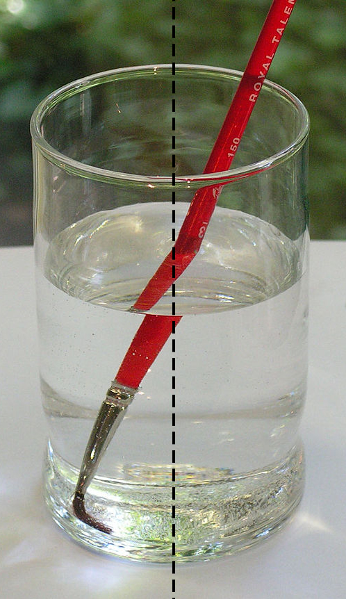

Normal is simply another term for a line drawn perpendicular (at right angles) to another line, in this case the interface between two mediums.
Calculation of RI
The refractive index (\(n\) or RI) is calculated using the equation below:

\(n = \frac{\color{darkred}{\sin i}}{\color{darkblue}{\sin r}}\)
On the whole conservators are not expected to calculate the refractive index, although they do need to be able to use the information it gives.
Calculation of RI Cont.
If you know the refractive index of any two materials, then you can calculate the amount that the light will be bent from Snell's law.

\(\require{color}\frac{\color{darkred}\text{Sine} \ i}{ \color{darkblue}\text{Sine} \ r} =\frac{\color{darkblue}\text{Refractive index B}}{ \color{darkred}\text{Refractive index A}}\)
\(\color{darkred}\text{Sine }\ i\ \times \ \text{Refractive index A} \color{black} = \color{darkblue}\text{Sine}\ r \times \text{Refractive index B}
\)
Sine of an Angle: Definition
The sine of an angle is calculated from the side lengths of a right angle triangle.

\(\sin \angle a = \frac{\text{Length of opposite side}}{\text{Length of hypoteneuse}}\)
Similarly,
\(\cos a = \frac{adjacent}{hypoteneuse}\)
\(\tan a = \frac{opposite}{adjacent}\)
Measurement of RI
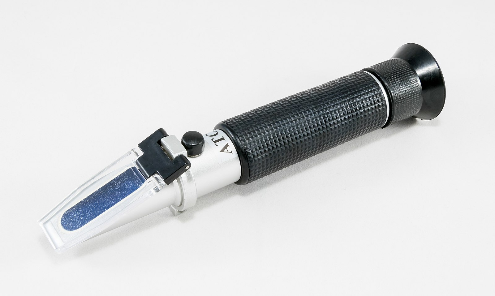
Refractive index is usually measured with some kind of refractometer.
Refractive Index: References
These articles include the use of the refractive index and can both be found at JAIC Online.
Refractive Index: Summary
In this section, you have learned:
- How visible light fits into the electromagnetic spectrum
- The equation that defines refractive index
- How to calculate the refractive index
- How Snell's law is used to calculate the amount light will be bent
Reflection
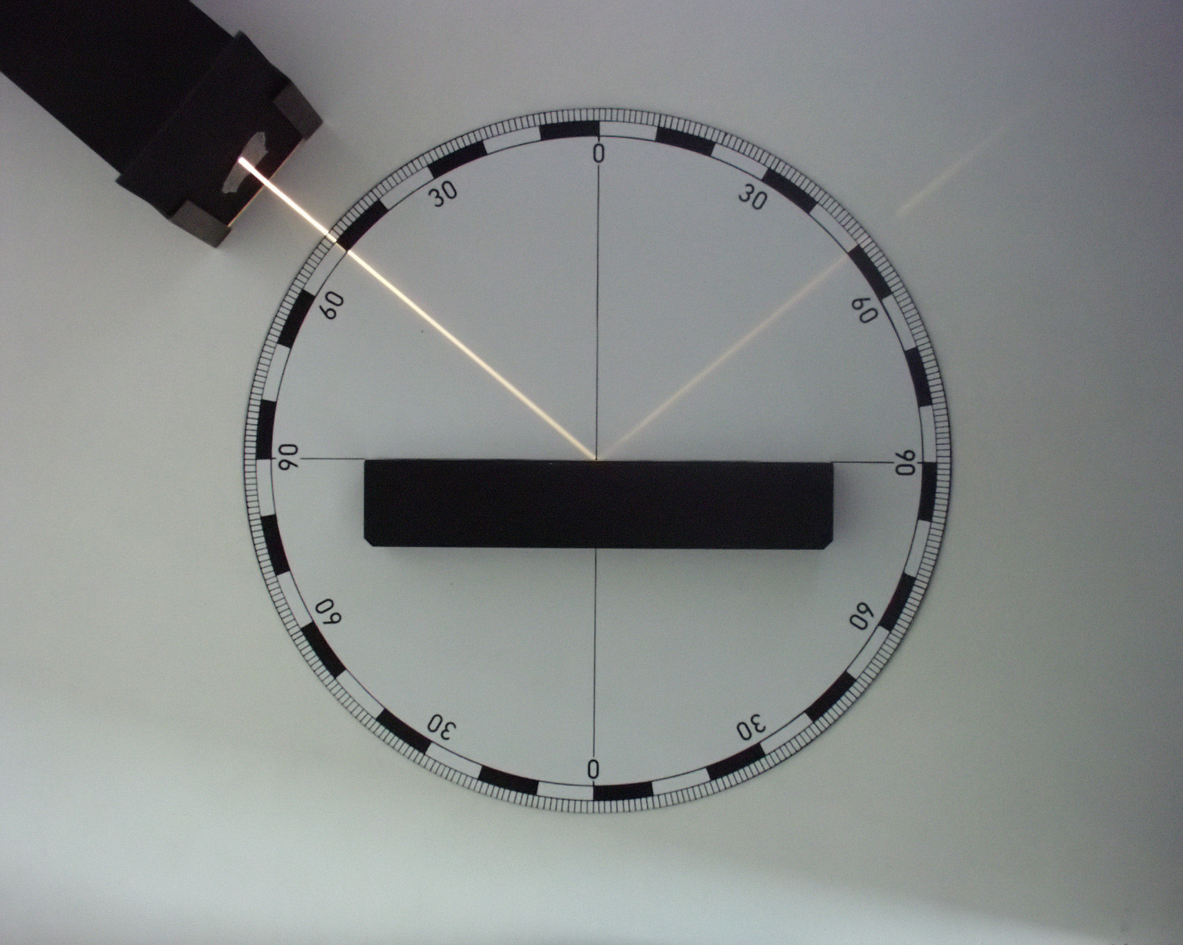
Reflection: Learning Objectives
After completing this section, you will be able to:
- Describe how light reflection contributes to color and texture of a surface
- Know the difference between specular and diffuse reflection
- Understand how the combination of reflection and refraction needs to be accounted for in exhibiting artwork
- Describe how the critical angle can be used to determine how much light is internally reflected
- List several practical applications of knowledge of the critical angle
Reflection, Color, and Texture
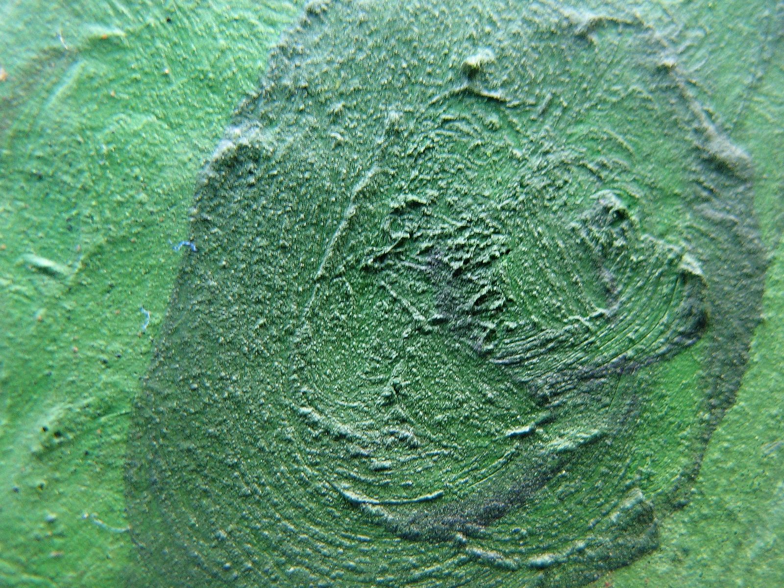
The way light reflects off an object determines, to a large extent, the color and texture of the surface.
This is important for filling and in-painting.
Specular Reflection
When light hits a smooth surface some of it is reflected and some of it is refracted. Reflection from a smooth surface, like a mirror, is called specular reflection.

Hubble Telescope Example
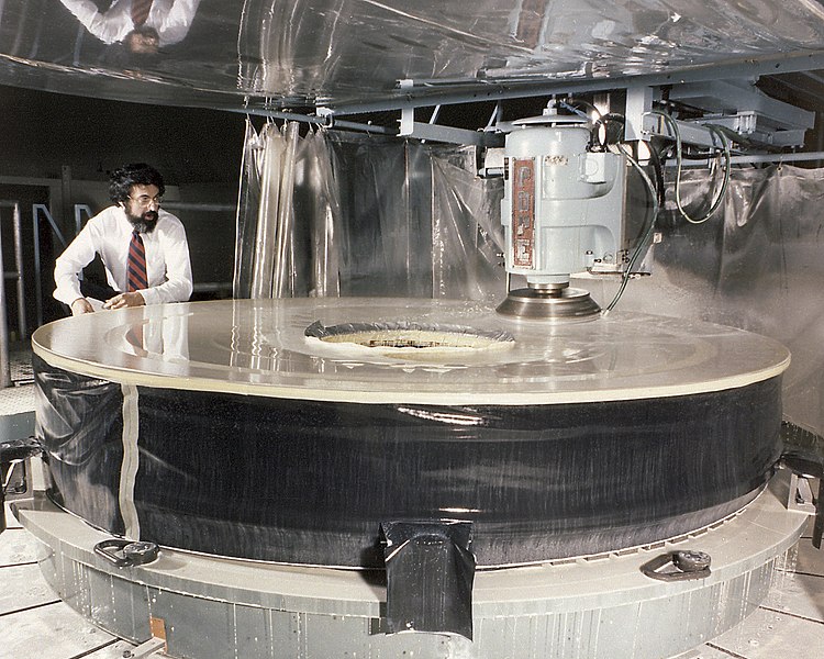
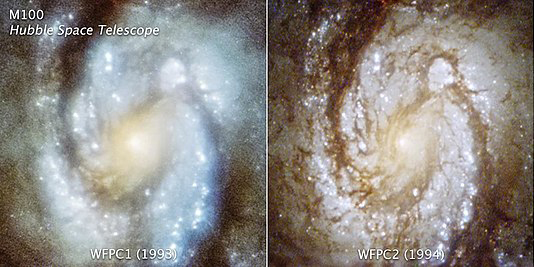
The mirror for the Hubble telescope was polished to within an accuracy of 30 nanometers. It took two years.
Diffuse Reflection
Light hitting a rough surface like a pigment particle is scattered.

Combination of Reflection and Refraction
Light is reflected and refracted when it hits the boundary between any two different materials. This can get quite complicated.
The amount of light that is reflected at each boundary depends on the differences in the refractive indices.
Combination of Reflection and Refraction
The combination of reflections and the refractive index of materials needs to be taken into account for exhibitions and picture framing.

Critical Angle
The critical angle depends on the ratio between the two refractive indices shown below.
When light travels from a lighter medium (low refractive index) to a denser medium (high refractive index) the light is bent towards the normal.
When light travels from a denser medium to a lighter one, the light is bent away from the normal.
If the light strikes the interface at a critical angle, all the light is reflected back into the denser medium.
Critical Angle
Light will be totally internally reflected if the following condition is met:
\(\frac{n_2}{n_1}\leq 1\)
The refractive index of the lighter medium divided by the refractive index of the denser medium is equal to or less than 1.
For light moving from glass into air (or into a vacuum), the critical angle is approximately 41.8º.
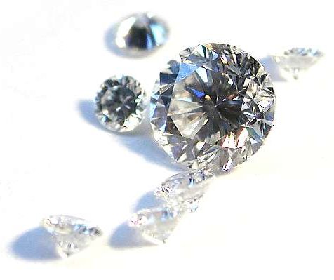
The critical angle for diamond is about 24.4º. Jewelers cut diamonds so that most of the light is internally reflected.
Application of Total Internal Reflection
We can find the physics of total internal reflection put to good use in the cool fiber optic lighting that is used in exhibitions and some scientific equipment. The fiber in fiber optics consists of:

More on Fiber Optics

The light is shone down a glass core that has a high refractive index.
The light reflects from the cladding which has a much smaller refractive index.
The light will reflect from the cladding and travel down the glass core even when the fiber is bent.
ATR FTIR
A similar concept is used in attenuated total reflectance Fourier-transform infrared spectroscopy (ATR FTIR)

Infrared light is shone along a sample cell. At each reflection point it enters the sample for a few microns. An absorption spectrum is produced from the sampling points.
Reflection: References
These articles on the concept of reflection can be found at JAIC Online.
Reflection: Summary
You have learned:
- How light reflection contributes to color and texture of a surface
- The difference between specular and diffuse reflection
- How the combination of reflection and refraction needs to be accounted for in exhibiting artwork
- How the critical angle can be used to determine how much light is internally reflected
- Several practical applications of knowledge of the critical angle
Credits
Researched and written by Sheila Fairbrass Siegler
Instructional Design by Cyrelle Gerson of Webucate Us
Project Management by Eric Pourchot
Special thanks to members of the Association of North American Graduate Programs in Conservation (ANAGPIC) and the AIC Board of Directors for reviewing these materials.
This project was conceived at a Directors Retreat organized by the Getty Conservation Institute and was developed with grant funding from the Getty Foundation.
Converted to HTML5 by Avery Bazemore, 2021
© 2008 Foundation for Advancement in Conservation