PARALOID B-72 AS A STRUCTURAL ADHESIVE AND AS A BARRIER WITHIN STRUCTURAL ADHESIVE BONDS: EVALUATIONS OF STRENGTH AND REVERSIBILITYJERRY PODANY, KATHLEEN M. GARLAND, WILLIAM R. FREEMAN, & JOE ROGERS
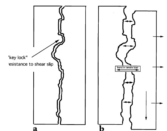
2 APPROACHES TO TESTINGMarble test coupons were prepared using a range of adhesives and the bonds evaluated by both shear and tensile tests. Shear testing (tests designed to place opposing loads along opposing faces of a bond) is the most common evaluation of adhesives, since the test coupons are more easily produced and since most demands on an adhesive bond in commercial applications are defined as shear. However, evaluations of the shear test results and the experience of preparing the test samples led the authors to also pursue tensile load evaluations and to increase the number of samples and range of adhesive mixtures tested. Tensile tests impose a force along the axial direction of a bond perpendicular to the bond plane. This kind of load is often prevalent in joints of reassembled largescale stone sculptures. An example of a common tensile load is the outstretched arm of the sculpture in figure 1. If we assume that a shear pin is not part of the joint in this particular example and that the assembly looks like figure 3a, then the forces acting upon the arm might at first appear to be only shear, that is, directly downward due to gravity and roughly parallel to the joint surface. However, should this joint derive from a fracture, the substrates will have a complex surface morphology, and the two surfaces will, to some degree, physically “lock” into place. On closer examination, it is easy to see that the direct downward movement of one surface relative to the other is blocked by the interlocking roughness of the two substrates (the coefficient of friction is high). If the arm is to move in a direction parallel to the joint surface (shear movement), one substrate must move away from the other in a perpendicular direction (fig. 3b) to overcome the “interlocking surfaces” of both substrates. The adhesive layer, as a result, experiences tensile load. Even if we were to introduce a shear pin,
|