SEISMIC STABILIZATION OF HISTORIC ADOBE STRUCTURESWILLIAM S. GINELL, & E. LEROY TOLLES
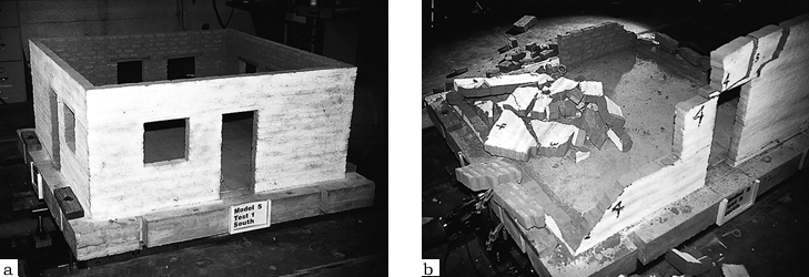
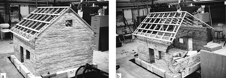
4 4. EVALUATION OF RETROFIT TECHNIQUESTo evaluate experimentally the concept of stabilization of historic adobe structures by the use of straps and center cores, a series of seismic simulation shaking table tests was carried out on model adobe buildings. The initial tests studied the effects of various combinations of straps and center cores on both the in-plane and out-of-plane behavior of adobe walls of varying height-to-thickness ratios (SL). Six roofless model buildings were constructed on a scale of 1:5 and were built up using molded adobe bricks and adobe mortar. Each model consisted of four walls, 148 cm square by 58 cm high, and had window and door openings on each wall (fig. 3). The models were rigidly attached to concrete bases that were anchored to the earthquake simulation shaking table at the John S. Blume Earthquake Engineering Center, Stanford University, California. Also tested were three 1:5 scale models constructed to simulate an actual building (fig. 4). The design was that of a tapanco-style building, a common southwestern United States design that includes attic floor-joist and rafter-type roof systems, load-bearing walls above the attic floor level, and highly vulnerable, non-load-bearing gable end walls.
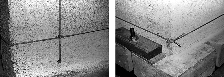
The straps used in these tests were 6 mm wide, woven, flat nylon strips that were applied on both sides of the wall and were tied at 30 cm intervals through holes in the wall using 1 mm diameter nylon cord ties (fig. 5). The wood bond beam was 30 mm wide by 6 mm thick and was attached to the top of the wall using 75 mm long, coarse thread drywall screws. Center core rods, 1.5 mm diameter, were inserted vertically in the wall, through the bond beam, and were attached to the beam with epoxy adhesive.
The shaking table was computer controlled, and each model was subjected to a series of table motions (test levels I to X) with increasing displacements based on the N21E component of the 1952 Taft earthquake in Kern County, California. Each succeeding displacement and acceleration was 20–30% larger than the previous one, up to a maximum of � 38 cm and 0.58 g in the prototype domain.1 The shaking table motion was uniaxial in the east-west direction so that the east and west walls of the models and the gable end walls of the tapanco models were out-of-plane. To evaluate the relative effects of orientation, two adjacent walls were retrofitted in the same way; therefore in-plane and out-of-plane results could be obtained simultaneously for a given type of retrofit. Various combinations of retrofit measures and SL were tested on each of the model adobe structures, and unretrofitted control models of both roofless and roofed types were also included in the test matrix. The duration of the ground motions was 20 seconds in the prototype domain and 4 seconds in the model domain. This is a long duration for the smaller tests but is short for the largest test. An earthquake of Richter magnitude 8 might last more than 1 minute. Even though these models buildings were subjected to repeated ground motions, which made the damage to the models cumulative, the combination of tests levels VIII, IX, and � taken together may be a reasonable representation of the largest ground motions to be expected in the California area. |