SEISMIC STABILIZATION OF HISTORIC ADOBE STRUCTURESWILLIAM S. GINELL, & E. LEROY TOLLES
ABSTRACT—ABSTRACT—Many historic adobe structures in the southwestern United States and throughout the world are vulnerable to destruction or damage by earthquakes. In the recent Northridge earthquake in Los Angeles, a significant number of the remaining, unretrofitted adobe structures dating to the 18th and early 19th century were extensively damaged. Yet it has been observed that many other adobes have performed well during large seismic events. Responses differ because low-strength adobe, when used in thick walls, develops cracks during seismic events, but these cracks do not necessarily lead to catastrophic building collapse. The concept of seismic retrofitting based on improving the stability of the adobe buildings, rather than the more conventional criterion of improving the strength, seems to be a valid approach. The objective of such a concept is to prevent walls from overturning by restricting the relative displacement of blocks formed following cracking, thereby enabling the structure to dissipate energy by friction and rocking without catastrophic collapse.Shaking table tests of model adobe buildings have been carried out. Various types of simple retrofitting measures that were evaluated were designed to be relatively noninvasive and respectful of the historic fabric of the building. These measures consisted of thin, flexible horizontal or vertical straps applied to both sides of walls and small diameter steel rods inserted within the walls used in conjunction with a thin wood bond beam. The intent of these measures was to provide overall structural continuity rather than strength improvement. The results of the tests involving nine 1:5 scale model buildings clearly demonstrated the effectiveness of the stability-based techniques. Wall height-to-thickness ratios were varied from 5 to 11, and maximum table displacements of �38 cm (prototype domain) were used. Some retrofitted models were able to withstand twice the displacement that resulted in collapse of an unretrofitted model. Additional tests carried out on two instrumented 1:2 scale model adobe buildings further demonstrated the effectiveness of the retrofitting measures. TITRE—Stabilisation sismique des structures historiques en adobe. R�SUM�—Beaucoup de structures historiques en adobe dans le sud-ouest des �tats-Unis et dans le monde entier sont passibles de destruction ou de dommages quand des s�ismes se produisent. Au cours du r�cent tremblement de terre de Northridge, pr�s de Los Angeles, plusieurs structures en adobe datant du 18�me et du d�but du 19�me si�cle et qui n'avaient pas �t� adapt�es, ont �t� s�v�rement endommag�es. Pourtant on a observ� que beaucoup d'autres b�timents en adobe ont bien support� de grands s�ismes. Les r�ponses aux secousses diff�rent parce que l'adobe n'est pas un mat�riel d'une grande solidit� et lorsqu'il est utilis� dans des murs �pais, il se l�zarde pendant les s�ismes. Cependant, ces fissures n'entra�nent pas n�cessairement l'effondrement catastrophique du b�timent. Le concept d'adaptation sismique, bas� sur l'am�lioration de la stabilit� des b�timents en adobe plut�t que sur le crit�re plus conventionnel d'am�lioration de la solidit�, semble �tre une mani�re valide d'aborder ce probl�me. L'objectif d'un tel concept est d'emp�cher que les murs ne s'effondrent en limitant le d�placement relatif des blocs form�s apr�s la fissuration et en permettant � la structure d'absorber l'�nergie par frottement et de vibrer sans s'effondrer.Des essais de secousse ont �t� r�alis�s en laboratoire sur des maquettes de b�timents en adobe. Maintes mesures d'adaptation ont �t� �valu�es et parmi celles-ci, plusieurs �taient simples et relativement discr�tes, afin de ne pas compromettre l'int�grit� historique du b�timent. Elles consistent en l'application de fines courroies flexibles horizontales ou verticales de chaque c�t� des murs et de tiges en acier de petit diam�tre ins�r�es dans les murs et utilis�es en combinaison avec une poutre de bois mince. Le but de ces mesures est de cr�er une continuit� structurale globale dans le b�timent, plut�t que d'am�liorer sa solidit�. Les r�sultats des essais sur neuf maquettes construites � l'�chelle 1:5 ont clairement d�montr� l'efficacit� des techniques bas�es sur la stabilit�. On a modifi� les rapports de hauteur versus �paisseur des murs de 5 � 11 et utilis� des d�placements maximum de table en laboratoire de plus ou moins 38 centim�tres (encore � l'�tape de prototype). Quelques maquettes dont les murs avaient �t� adapt�s ont r�sist� � un d�placement deux fois plus intense que d'autres qui caus�rent l'effondrement des maquettes avec des murs non adapt�s. Des essais suppl�mentaires effectu�s sur deux maquettes en adobe � l'�chelle 1:2 ont confirm� l'efficacit� des mesures d'adaptation. TITULO—Establilizaci�n s�smica de estructuras hist�ricas de adobe. RESUMEN—Muchas estructuras hist�ricas del sudoeste de los Estados Unidos y de todas partes del mundo son vulnerables a destrucci�n o da�o por terremotos. Durante el terremoto de Northridge ocurrido recientemente en Los Angeles, un n�mero significativo de restos de estructuras de adobe, que no ten�an refuerzos antis�smicos, de los siglos XVIII y XIX se da�aron extensamente. Sin embargo, se ha observado que muchas otras estructuras de adobe se han desempe�ado bien durante grandes s�smos. Las respuestas difieren porque cuando el adobe de baja resistencia es utilizado en paredes gruesas, durante eventos s�smicos desarrolla grietas que no necesariamente llevan al colapso del edificio. El concepto de refuerzo antis�smico basado en mejorar la estabilidad de las construcciones de adobe en vez del criterio m�s convencional de mejorar la resistencia, parece ser v�lido. El objetivo de este concepto es prevenir que las paredes se derrumben al restringir el desplazamiento relativo de bloques que se forman despu�s que se producen los agrietamientos, de manera que la estructura disipe energ�a por frici�n y balanceo sin que exista un colapso catastr�fico.Se llevaron a cabo pruebas sobre modelos de edficios de adobe en mesas de agitaci�n. Varios tipos de medidas sencillas de refuerzo antis�smico fueron evaluadas. Las mismas fueron dise�adas para ser relativamente no invasivas y respetuosas del tejido hist�rico del edificio. Consistieron en la aplicaci�n de bandas delgadas y flexibles, horizontales y verticales en ambos costados de las paredes y de varillas de acero de di�metro peque�o insertadas en el interior de las paredes y utilizadas a un tiempo con una viga de enlace de madera delgada. La intenci�n de estas medidas, m�s que mejorar la resistencia era proveer continuidad estructural generalizada. Los resultados de estas pruebas que involucaron nueve modelos de edificios en escala 1:5 demostraron claramente la efectividad de las t�cnicas basadas en la estabilidad. Las relaciones entre la altura y el espesor de la pared fueron variadas de 5 a 11 y se utiliz� un m�ximo de desplazamiento en la mesa de �38 cm. (esfera de influencia del prototipo). Algunos modelos con refuerzo antis�smico fueron capaces de soportar el doble del desplazamiento que hacia colapsar un modelo sin refuerzo. Pruebas adicionales llevadas a cabo en dos modelos de edificios de adobe en escala 1:2 demostraron la efectividad de las medidas antis�smicas. 1 1. INTRODUCTIONMany of the early structures that date back to the Spanish Colonial period in the southwestern United States were built of mud brick or adobe. The materials available for construction of many of the early churches, missions, and houses were generally limited to those that were locally available and easily worked by local artisans. Adobe has many favorable characteristics for construction in arid regions: it provides good thermal insulation; the clayey soil from which adobe bricks are made is ubiquitous; the skill and experience required for building adobe structures are minimal; and building construction does not require the use of scarce fuel. As a consequence of their age and design and the functions they performed, surviving adobe buildings are among the most historically and culturally significant structures in their communities. Historically, the seismic performance of adobe structures, as well as those of stone and other forms of unreinforced masonry, has in many cases been very poor. The seismic behavior of such buildings is characterized by sudden, dramatic, and catastrophic failures. The local or general collapse of adobe structures is often accompanied by a high likelihood of serious injuries and loss of life. Yet it has been observed that some adobes have withstood repeated severe earthquake ground motions without total collapse. Generally, the evaluation of the engineering community is that adobe buildings, as a class, pose the highest earthquake risks among the various building types, and the standard engineering analyses and approaches to the design of retrofits are not applicable to these structures. Following the emergence of modern construction methods in which steel and reinforced concrete replaced brick and stone as principal building materials, structural designs were developed that could withstand environmental loads (wind and earthquake) and perform in a relatively predictable and acceptable way. Steel and reinforced concrete are ductile materials that have linear elastic properties and good postelastic strength characteristics. After yielding, these materials maintain most of their strength while undergoing substantial plastic deformations, and they can be analyzed with reasonable accuracy using analytic or computational methods. In contrast, after cracks are initiated, the behavior of brittle, unreinforced materials, such as stone, brick, or adobe, is extremely difficult to predict even with today's advanced computational capabilities. Even if computational results could be generated, the results would not be accurate. In a brittle material, once yielding occurs, cracks develop and there is a complete loss of tensile strength. After cracks have developed, the seismic behavior of adobe buildings is dominated by the interactions among large, cracked sections of the walls that rock out-of-plane and collide or rub against each other in-plane. The fundamentals of the postelastic behavior of adobe are entirely different from those of ductile building materials because adobe is a brittle material. Once a typical unreinforced adobe wall has cracked, the tensile strength of the wall is completely lost, but so long as the wall remains upright and stable, it can still carry vertical loads. Cracks in adobe walls may occur from seismic forces, from settlement of the foundation, or from internal loads such as roof beams. However, even though the tensile strength of the wall material has been lost, the structure may retain its ability to remain standing. The thickness of typical historic adobe walls makes these walls difficult to destabilize even when they are severely cracked. The support provided at the tops of the walls by a roof system may add additional stability to the walls, especially when the roof system is anchored to the walls. In many adobe buildings, the height-to-thickness (slenderness) ratios may be less than 5 and the walls can be 1–2 m thick; both factors make wall overturning unlikely. Some seismic retrofit techniques can be used on other, thinner wall structures to improve stability and to reduce the differential displacements of the cracked sections during an earthquake. Reinforced concrete bond beams, placed at the tops of walls below the roof, are often recommended for the upgrading of existing adobe buildings (California State Historical Building Code 1999). The function of bond beams is to provide lateral support and continuity at the tops of the walls. However, the installation of a bond beam usually requires the removal of the roof system, a very invasive and destructive procedure. The design of bond beams is often based upon elastic design criteria, which result in a very stiff bond beam. After cracks in the adobe walls develop during an earthquake, the stiffness of the bond beam may exceed the stiffness of the walls by 2 or 3 orders of magnitude. Adobe walls have been observed to pull out from underneath bond beams during an earthquake due to the difference in stiffness between the bond beam and the cracked wall sections and the lack of a positive connection between the bond beam and the adobe walls. In prior years, some gains had been made by the engineering community in developing retrofit measures that were seemingly more sensitive to the conservation of historic fabric. Nevertheless, there was very little information about how these less-intrusive retrofit systems would, in fact, behave. In the late 1970s, a proposed retrofit system for the Cooper-Molera adobe building in Monterey, California, used interior and exterior wire mesh to enclose the adobe walls (Forell/Elesser Engineers 1977). This system was not implemented because there was little information on the performance of such a retrofit and concerns that the system would destroy too much of the historic fabric of the building. The system actually installed at Cooper-Molera consisted of reinforced concrete posts and beams in and on the walls (Forell/Elesser Engineers 1977–78), but this system, too, had a large negative impact on the historic fabric (Scawthorn and Becker 1986). A modified wire mesh system was tested later and was shown to be effective, but it remains a too highly intrusive technique for use on historic structures. All too often, the design of seismic upgrading modifications to existing hazardous buildings has focused on the goal of providing maximum life safety to occupants with little consideration being given to the limitation of damage to the buildings (Thomasen and Searls 1991). Structural stability is the fundamental requirement for the adequate performance of adobe buildings during large earthquakes and should be the principal guide for designing appropriate retrofit measures. The walls of adobe buildings will crack during moderate to large earthquakes because adobe walls are massive and both the adobe brick and adobe mortar are low-strength materials. The massive walls respond to the large inertial forces that result from seismic ground accelerations, and they have relatively little strength to resist these forces. After cracks have developed, it is essential that the cracked elements of the structure remain in place and be able to carry vertical loads. To achieve structural stability, it is necessary to mobilize adobe's very favorable postcracking energy dissipation characteristics while limiting relative displacements between adjacent cracked blocks. From our investigations, we have concluded that a stability-based approach to retrofitting historic adobe buildings can be the most effective method for providing life safety and for limiting the amount of damage during moderate to large earthquakes. The purpose of a stability-based approach is to prevent severe structural damage and collapse. Application of this approach should recognize the limitations of adobe while taking advantage of the beneficial, inherent structural characteristics of many historic adobe buildings—thick walls that are inherently stable and have a great potential for absorbing energy. These stability and energy absorption characteristics can be greatly enhanced by the application of a number of simple seismic improvement techniques. Implementation of any stability-based approach must take into consideration that the seismic upgrading of historic buildings embraces two distinct and apparently conflicting goals:
These goals are often perceived as being fundamentally opposed. Using current seismic retrofitting practices, substantial alterations of structures are usually required and often involve new structural systems and substantial removal or replacement of building materials. Although historic structures so modified and fundamentally altered can be stabilized, they can lose much of their authenticity. As a result, the conflict is often seen as an either/or proposition:
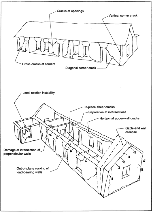
Faced with the apparent conflict between the unacceptable seismic hazard posed by many adobe buildings and the unacceptable conservation consequences of conventional retrofitting approaches, the Getty Seismic Adobe Project (GSAP) was initiated to develop and evaluate procedures that would recognize the simultaneous needs for achieving life safety while preserving the historic fabric and authenticity of the building. In this project, we have formulated a retrofitting philosophy that is consistent with these objectives and is based on improving the stability of the adobe structure rather than improving its strength. The physical methods for carrying this philosophy out are described below, and they have been tested using 1:5 and 1:2 scale model adobe buildings that were shaken on earthquake simulation facilities in California and in the Republic of Macedonia. Some of the results of these tests are given below. 2 2. THE NATURE OF ADOBE STRUCTURE FAILUREIn adobe wall structures, cracking is almost certain to occur during seismic ground motions when the stresses in the wall exceed the tensile capacity of the adobe material. While the building is undamaged it will perform elastically, but as cracks develop, the dynamic vibrational characteristics undergo significant changes: the fundamental vibration frequency decreases dramatically and the displacements increase by 2 or 3 orders of magnitude. Motion along cracks becomes substantial as cracked surfaces intersect to form independent blocks of material. When the cracks fully develop, each wall becomes an assemblage of broken adobe blocks rather than a monolithic element, and this condition can lead to the collapse of the structure. The primary cause of the most often observed damage is the low tensile strength of the adobe bricks and mortar. Both shear and flexural stresses develop because of the low tensile strength of these materials. Typical failure typologies observed in historic adobe buildings are shown in figure 1. Forces parallel to the plane of the wall (in-plane forces) cause tensile stresses and diagonal cracking. Forces perpendicular to the plane of the wall (out-of-plane forces) cause flexural stresses, cracking, and wall rocking as shown in the long solid wall. Further development of the cracks in the long wall can result in a classic bearing wall failure. The walls typically fall outward, allowing the heavy tile or earthen roofs to collapse, killing occupants trapped inside. The failure of building corners results from a combination of flexural and tensile stresses. Once the corners have failed, the adjacent walls are more likely to fail out-of-plane and overturn. Tensile failure at the junction between perpendicular walls is another common failure mode. Interior partitions are often butted-up to exterior walls with no positive connection between the masonry of the adjoining walls. Gable end wall cracking, collapse, or overturning are the most commonly observed serious damage modes.
Using strength and ductility as fundamental survival criteria, it has been assumed that adobe buildings should not be able to resist the damaging effects of large seismic events. Yet many adobes, although cracked, have retained their stability and have not collapsed catastrophically during earthquakes. Therefore, a retrofitting design approach based on achieving stability, rather than improving strength, should be the most effective method for providing life safety while minimizing damage during moderate to large earthquakes. This design philosophy accepts the fact that although adobe has little material ductility, other characteristics of adobe buildings can be used to develop the needed structural ductility that is important in determining the seismic performance of the building. An important parameter in this regard is the relationship between the adobe wall thickness and the associated height-to-thickness ratio, SL (Bariola 1991). In the context of the work reported here, values of SL associated with estimated seismic effects on adobe walls are given in table 1.
For thin-walled adobe buildings, collapse is imminent once the walls have cracked, and therefore a thin-walled building has little structural ductility. For moderate- to thick-walled adobe buildings, cracks result in the formation of adobe blocks whose relative displacements can become very large, and both in-plane and out-of-plane collapse (overturning) become the principal failure modes. Failure in this sense refers to an adobe wall that cannot support itself or other loads. Thin walls that are not load-bearing are most susceptible to overturning, but moderate to thick load-bearing walls are more stable because displacements are limited by increased interblock friction and by connections to the roof or floor systems. Gable adobe end walls are particularly vulnerable to overturning because SL is usually large and the walls are not load-bearing. However, the challenge that was faced in the design of a stability-based retrofit was not how to prevent cracking (an inevitable consequence of an earthquake that will not necessarily result in structural collapse) but how to minimize the relative displacement of the adobe block wall segments so that overturning and loss of roof support do not occur. 3 3. SEISMIC STABILITY IMPROVEMENT TECHNIQUESA stability-based retrofit system is intended to prevent wall overturning by limiting the relative displacement between adjacent cracked wall segments and by improving the overall structural continuity of the building. A key feature of this concept is that movement across cracks and rocking should not be prevented but should be restrained so that seismic energy can be dissipated in rocking and as friction at the cracked interfaces. If a retrofitting measure is too strong or too stiff, failure of the structurally weak adobe will occur adjacent to the retrofit. To validate the stability-based retrofit concept, several restraint techniques have been studied and their effectiveness evaluated during shaking table tests of scale model adobe structures. The retrofit measures tested are listed in table 2 for models without roofs. These techniques were also applied to models with a roof, gable end walls, and an attic structure. Partial wood diaphragms and dowels that connected the walls and roof to improve continuity were also tested.
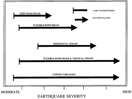
The applicability of each of the retrofitting measures can vary depending on the relative severity of the earthquake, as illustrated schematically in figure 2. A stiff bond beam may have an effect on elastic performance but may be so stiff that the connection between the bond beam and the adobe fails during moderate ground motions. This relationship is especially true when there is no positive connection between the bond beam and the adobe. A more flexible bond beam that is well anchored to the walls may have negligible effects on the elastic behavior but is more than stiff enough to have a substantial effect on the postelastic performance.
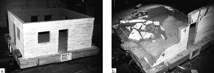
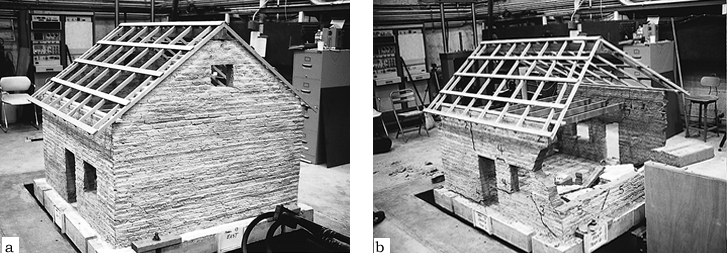
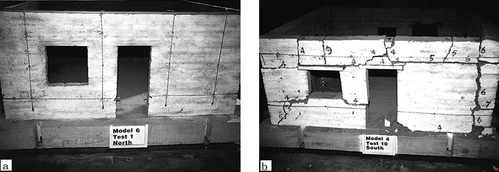
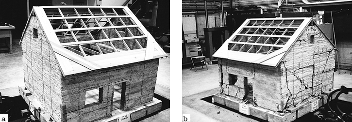
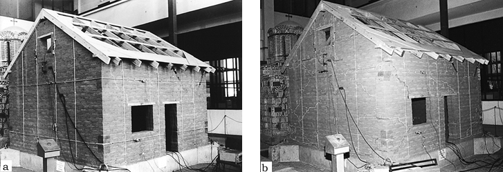
The walls must be cracked and begin to move before flexible, horizontal straps become effective. After cracking has developed, these straps can greatly decrease the risk of collapse by providing some restraint against excessive out-of-plane movements and by providing continuity between cracked sections of the walls. Vertical straps and a flexible bond beam do not change the elastic behavior or the behavior when damage is small, but during severe earthquakes, they can greatly reduce the relative displacements of the cracked wall sections and prevent overturning. 4 4. EVALUATION OF RETROFIT TECHNIQUESTo evaluate experimentally the concept of stabilization of historic adobe structures by the use of straps and center cores, a series of seismic simulation shaking table tests was carried out on model adobe buildings. The initial tests studied the effects of various combinations of straps and center cores on both the in-plane and out-of-plane behavior of adobe walls of varying height-to-thickness ratios (SL). Six roofless model buildings were constructed on a scale of 1:5 and were built up using molded adobe bricks and adobe mortar. Each model consisted of four walls, 148 cm square by 58 cm high, and had window and door openings on each wall (fig. 3). The models were rigidly attached to concrete bases that were anchored to the earthquake simulation shaking table at the John S. Blume Earthquake Engineering Center, Stanford University, California. Also tested were three 1:5 scale models constructed to simulate an actual building (fig. 4). The design was that of a tapanco-style building, a common southwestern United States design that includes attic floor-joist and rafter-type roof systems, load-bearing walls above the attic floor level, and highly vulnerable, non-load-bearing gable end walls.
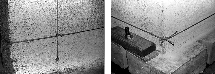
The straps used in these tests were 6 mm wide, woven, flat nylon strips that were applied on both sides of the wall and were tied at 30 cm intervals through holes in the wall using 1 mm diameter nylon cord ties (fig. 5). The wood bond beam was 30 mm wide by 6 mm thick and was attached to the top of the wall using 75 mm long, coarse thread drywall screws. Center core rods, 1.5 mm diameter, were inserted vertically in the wall, through the bond beam, and were attached to the beam with epoxy adhesive.
The shaking table was computer controlled, and each model was subjected to a series of table motions (test levels I to X) with increasing displacements based on the N21E component of the 1952 Taft earthquake in Kern County, California. Each succeeding displacement and acceleration was 20–30% larger than the previous one, up to a maximum of � 38 cm and 0.58 g in the prototype domain.1 The shaking table motion was uniaxial in the east-west direction so that the east and west walls of the models and the gable end walls of the tapanco models were out-of-plane. To evaluate the relative effects of orientation, two adjacent walls were retrofitted in the same way; therefore in-plane and out-of-plane results could be obtained simultaneously for a given type of retrofit. Various combinations of retrofit measures and SL were tested on each of the model adobe structures, and unretrofitted control models of both roofless and roofed types were also included in the test matrix. The duration of the ground motions was 20 seconds in the prototype domain and 4 seconds in the model domain. This is a long duration for the smaller tests but is short for the largest test. An earthquake of Richter magnitude 8 might last more than 1 minute. Even though these models buildings were subjected to repeated ground motions, which made the damage to the models cumulative, the combination of tests levels VIII, IX, and � taken together may be a reasonable representation of the largest ground motions to be expected in the California area. 5 5. DOCUMENTATIONThe tests were extensively documented with drawings, photographs, and videotape. The acceleration and displacement histories of the shaking table during each test were recorded digitally. Still photographs were taken to record the damage to each wall of each model after every test. The dynamic motion of each test model was recorded on videotape. Four video cameras were activated at the four corners of the model to record the motion of each of the four walls. It was important to record the dynamic motions of the models from all angles to be able to study the motion in detail after the testing was completed. During the test sequence the cracks were numbered as they appeared, and the number of each crack coincided with the test number in which the crack occurred. 6 6. SHAKING TABLE TEST RESULTS ON 1:5 SCALE MODELSThe principal end results of the tests are summarized in table 3. Typically, cracks were initiated in the adobe walls during test levels III or IV at shaking table acceleration values of 0.23 g and 0.28 g, respectively. Cracks continued to develop during test levels V and VI, after which the principal cracked block sections had been defined and their location then determined the nature of seismic performance of the model during the succeeding tests (test levels VII and above).
Unretrofitted models collapsed during test levels V or VI (see fig. 3). These test levels had an acceleration value of 0.32 to 0.40 g, and, more important, the peak displacements were approximately 16.5 to 24.8 cm in the prototype domain. In the prototype domain, thin walls (SL=11) were approximately 36 cm thick, moderate walls (SL=7.5) were 53 cm thick, and thick walls (SL=5) were 79 cm thick. Very high accelerations will not destabilize adobe walls if the frequency is high and the displacements are small. If the displacements are small, the base input may have large accelerations, but without large displacements, it is nearly impossible to destabilize the thick walls that are typical of many historic adobe buildings. Lightly retrofitted models were able to withstand somewhat higher test levels (fig. 6). Thin walls, with a bond beam and local ties, collapsed out-of-plane during test level VIII but the in-plane wall, with the same retrofit system, did not collapse until test level IX. The thick walls with horizontal straps remained standing through test level � while the moderate walls, with the same retrofit system, collapsed during test level X. Other models, with retrofit systems more complete than the lightly retrofitted models, showed greater resilience to extended, strong table motions. The addition of either vertical straps or center core rods greatly improved overall structural performance at the higher test levels, but the walls with center core rods sustained less damage through the test sequence than the walls with vertical straps only. Walls with horizontal and vertical retrofit measures continued to behave well through repetitions of test level X, and there were no indications of imminent collapse.
The results of the retrofitted tapanco model tests demonstrated the dramatic improvement in stability afforded by the wall retrofits and the continuity-assuring roof-to-wall attachments. Especially significant were the stability and damage control improvements that were provided by the thin center core rods (fig. 7).
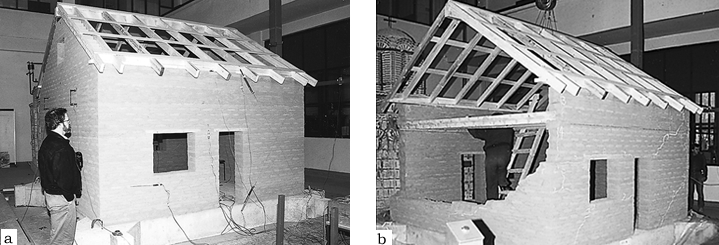
7 7. SHAKING TABLE TESTS ON 1:2 SCALE MODELSOne factor that could not be assessed in the small model tests was the effect of gravity on the behavior of massive, cracked, adobe block sections. Energy dissipation by friction between the moving blocks is dependent on the mass of the blocks, a factor that cannot be simulated accurately using normal density adobe in scale models. Testing of full-scale models would be prohibitively costly, and only one facility in the world (in Japan) has the capability of performing a full-scale test. Accordingly, half-scale (1:2) models, one retrofitted and the other not, were constructed and tested. These tests were performed at the 5 m square shaking table facility at the Institute of Earthquake Engineering and Engineering Seismology (IZIIS) of the University “SS Cyril and Methodius” in Skopje, Republic of Macedonia. The models constructed were of the same tapanco design as those of the 1:5 scale models 8 and 9 tested previously. Adobe materials strength tests and tests of assembled adobe wall segments were performed to try to match the properties of the California adobe used on the smaller models. However, the strength properties of the Skopje adobe proved to be lower, but it was probably more representative of the typical adobe, especially historic adobe, that is found throughout the world. The difference in strength affects only the initiation of cracks and should have had little effect on the postelastic dynamic behavior of the walls. The model dimensions were 3.7 by 3.7 m square by 3 m high with an SL = 7.4 (fig. 8). Instrumentation was installed for measuring both wall displacements at various locations and stresses in the walls and straps during the tests. Wall motions and crack damage were monitored by video and still photography in the same way as in the small model tests.
The retrofitting measures consisted of the following:
The west and the south walls were retrofitted with four vertical center core rods placed at regular intervals. During the construction, cavities 3 cm in diameter were formed in these walls using plastic tubes. After completion of the model, ribbed steel rods, 14 mm in diameter, were placed in these cavities, and the space around them was filled with an epoxy-adobe grout. The retrofitting measures for the east and the north walls were vertical nylon straps placed at regular intervals. Four vertical straps were used on both sides of the walls. The straps went over the tops of the walls and through drilled holes at the base of the wall. Small diameter straps were used for cross ties between these straps. Two horizontal straps were placed on each of the four walls. The upper horizontal strap was located at the attic floor line and was attached to the floor system. The lower horizontal strap was located just below the bottom of the window on both sides of each wall section. Partial wood diaphragms were added to the attic floor and roof, and wood blockings were inserted between the floor joists, which were anchored to the walls. The adobe parts of the model were cured for 80 days, and retrofitting was installed just prior to the shaking table tests. The first crack in the unretrofitted adobe structure occurred during the test at an acceleration level of 0.17 g and input displacement of 5.8 cm, and, owing to the loss of structural integrity, separation of the out-of-plane walls occurred. The level at which the elastic, first cracking, behavior of unretrofitted adobe building walls occurs is not usually significant because the walls of most historic buildings could already have some crack damage from water, earthquakes, or foundation settlement. During subsequent tests, many additional cracks appeared in all walls, and after the final dynamic test, the model was heavily damaged. Development of almost vertical and horizontal cracks was evident in the out-of-plane walls. After the final test the model suffered large nonlinear damage that resulted in the collapse of the east gable end wall (see fig. 8). The first crack in the retrofitted model structure occurred during the test at an acceleration level of 0.23 g and input displacement of 7.6 cm. Out-of-plane instability did not occur until the base motion (peak-to-peak) reached 75% or more of the thickness of the walls. Instability occurred at the start of test level VIII but might have occurred during test level VII if not for the stabilizing effects of the roof system. The maximum displacement of test level VII was 19 cm, and the peak-to-peak displacement was about 30 cm. The thickness of the walls was 41 cm, all in the prototype domain. During the subsequent tests, many cracks appeared in the east and north walls that were retrofitted using vertical and horizontal nylon straps. On the west and south walls that were retrofitted using vertical center core rods, fewer cracks were found. The failure mechanism in the final stage is the occurrence and development of diagonal cracks in the in-plane walls due to shear effects and large nonlinear damage in the out-of plane walls. After the final dynamic test, the east gable end wall of the model was heavily damaged, but none of the walls collapsed (fig. 9). In these tests, the gable end wall of the unretrofitted model collapsed at about the same level of shaking intensity as the smaller scale models. The crack patterns, too, were very similar. In the retrofitted model, the nylon straps and, especially, the center core rods proved very effective in preventing collapse.
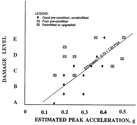
8 8. ASSESSMENT OF THE RETROFIT MEASURESBoth systems used on the retrofitted model had significant impacts on the structural performance of the model. The first requirement of a retrofit system is to reduce (or eliminate) the collapse hazard of the building, and each method proved very successful in this regard. 8.1 8.1 STRAPS AND CABLESThe advantage to the strapping system is that the installation has minimal impact on the historic fabric and is also, to some extent, reversible. The retrofit method using vertical straps is most effective for reducing the risk of out-of-plane collapse but had little or no effect on the initiation and early development of crack damage. When displacements or offsets become significant, the strapping system controls the relative displacement of cracked sections of walls that could otherwise lead to instability. When coupled with anchorage to the roof and/or floor system, the out-of-plane overturning or midheight collapse can be prevented. In-plane damage is much less affected by vertical straps generally, because in-plane offsets are of smaller magnitude and more likely to remain after the dynamic motions are completed. Straps can prevent large displacements but not small crack offsets, and they can prevent piers between doors and windows from becoming unstable. 8.2 8.2 CENTER CORE RODSThe center core rods were found to be particularly effective. The initiation of cracks was delayed, and some cracks in the in-plane walls that started at the corners of the door and window propagated to the center core rod and then stopped for one or two more tests. The cracks never became severe. In the out-of-plane walls the center core rods acted as reinforcing elements. The adobe-epoxy grout provided effective shear transfer between the adobe and the steel rods. The epoxy unevenly soaked into the adobe especially at the mortar joints and therefore provided a positive attachment between the steel rods and the adobe wall. The walls with center core rods were then able to act as structurally reinforced elements in the vertical direction. 9 9. COMPARISON OF LARGE-SCALE (1:2) AND SMALL-SCALE (1:5) MODELSThe performance of large-scale and small-scale model buildings was very similar in many ways. The general development of cracks, the types of cracks, and the failure modes were similar. The effects of the retrofitting measures on the building's behavior were also similar. For the most part, the effects observed in the small-scale model tests were also observed in the large-scale models. The principal physical difference between the large-scale and small-scale models was the lower gravity loads in the smaller models. These models do not fully replicate gravity loads because the mass loading at the base of the 1:5 model wall was very similar to that at the top of the wall, which was not the case for the half-scale building. As a result, there were small differences in both the out-of-plane and in-plane wall performance. On the other hand, the global performance was very similar. The clearest difference in the behavior of the large-scale and small-scale models concerned the diagonal cracks in the in-plane walls. Diagonal cracks allow displacements that are cumulative and slippage that is exacerbated by vertical loads. As a result, diagonal cracks were a larger problem in the large-scale model and would be expected to be at least as serious a problem in full-scale buildings. Diagonal cracks near the end of piers and walls are of particular concern in real buildings. Overturning of walls is less of a problem in full-scale buildings compared to small-scale models because the vertical loads resist overturning. On the other hand, the condition of the base of the walls in the model buildings was very good, while in many actual adobe buildings, the adobe at the base of the walls may have been weakened by exposure to moisture. 10 10. NORTHRIDGE EARTHQUAKEThe occurrence of the Northridge earthquake in January 1994 in California provided a unique opportunity to compare the actual damage sustained by existing, real adobe structures with the damage observed during the model adobe building shaking table tests. Shortly after the earthquake, a survey of 19 historic adobe buildings located in Los Angeles and Ventura Counties was conducted by a team consisting of two engineers, an architect, and an architectural historian. The intent of the survey was to document the damage to the buildings, correlate the damage with measured ground movements and building condition, and provide information to owners, building officials, cultural resource managers, architects, and engineers that would assist in the understanding of seismic threats to such structures. Based on the information generated during the survey (Tolles et al. 1996), estimates were made regarding expected damage to historic adobe buildings as a function of estimated peak ground acceleration. For well-maintained historic adobes, figure 10 shows the relationship between acceleration and damage. Ground acceleration in the range of 0.1 to 0.2 g seems to be required to initiate damage in such adobe buildings. At this level of ground motion, cracks begin to form at door and window openings and at the intersections of perpendicular walls. At the historic adobe building sites studied where the acceleration was in this range, one was undamaged, two suffered slight damage, while another suffered slight to moderate damage. These adobes had been well maintained and had not been reinforced or retrofitted. At acceleration levels of about 0.4 g, the damage was found to be more extensive throughout the structure.
Pre-existing conditions greatly affected the observed damage level. In figure 10, all data on buildings with pre-existing water and earthquake damage were found above the expected damage line for well-maintained adobes, indicating that severe damage can be expected for buildings in poor condition. Even for ground motions of moderate intensity (0.1 to 0.2 g), poorly maintained buildings are likely to suffer substantial damage. Comparison of laboratory tests and field observations show good correlation, and the important observations can be summarized as follows:
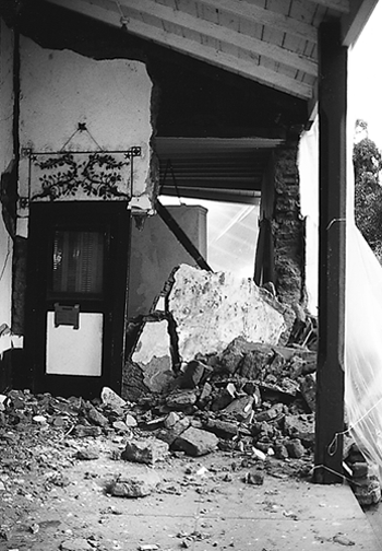
These observations are valid for typical historic adobe buildings that had been well maintained, had moderately thick or thick walls, and adobe of average strength. The presence of higher-strength adobe material may delay the onset of cracking. Low-strength adobe or previously damaged walls will have a negative impact on the performance, and thinner walls will be more likely to collapse. Many of the damage typologies observed in the field after the Northridge earthquake were also observed in the 1:5 scale model buildings. The typical out-of-plane wall failures were observed in numerous historic adobe buildings, and the crack patterns resulting from out-of-plane flexural failure and gable end failure were also typical failure patterns observed in the field and in the laboratory. The out-of-plane collapse of load-bearing walls was observed at only one site (fig. 11). However, this failure was not the result of overturning but was caused by moisture damage at the base of the wall, which is yet a different, but important, failure mode.
At corners, vertical and diagonal cracks in the models were observed and were similar to those observed in the field, but in-plane shear cracks occurred less frequently. Mechanical tests of the 1:5 scale adobe brick assemblies showed that the shear strength was proportionately higher compared to the compressive or flexural strengths. Therefore, in-plane shear cracks are less likely to occur than vertical or diagonal cracks. In general, the overall crack patterns observed in the model buildings were similar to those found in historic adobe buildings after the Northridge earthquake. The nature of the postelastic behavior is largely dependent upon location of the crack patterns and the resulting movement of the cracked wall sections. The dynamic motions of the models would then be expected to be similar to those found in the field. 11 11. CONCLUSIONSThe results of the studies performed as part of the Getty Seismic Adobe Project have shown that effective seismic retrofit measures can be implemented with only minor effects on historic building fabric. Information is now available to go beyond the pre-existing conflict between the conservation community's desire to preserve these buildings and the rightful concerns for life safety. The retrofit measures developed and tested in this research project can effectively provide for life safety by minimizing the possibility of catastrophic collapse while having a minimal impact on the historic building fabric. In the latter case, straps can be recessed into chases in the wall and covered with adobe rendering. Where wall painting or decorative elements exist on wall surfaces and the grooving of walls to accommodate straps would not be permitted, center cores may be used without major intervention damage. This research effort has provided the necessary technical information to justify the use of several minimally intrusive retrofit measures. The major accomplishments of the project were:
The results of the survey and their correlation with experimental data are significant and provide a large amount of information that can be useful in understanding the performance of historic adobe buildings and in developing further techniques for retrofitting this type of building. The GSAP program has been successful in using a multidisciplinary approach throughout the research effort, and the concern for protecting historic fabric, as well as life safety, was a constant theme that guided the design and implementation of the studies. NOTES1.. The term “prototype domain” refers to the dimensions and characteristics of the full-size structure and the parameters of the real earthquake. “Model domain” refers to those of the scale model and the test earthquake, which are reduced in value by some function of the scale factor that is not necessarily linear. ACKNOWLEDGEMENTSThe authors would like to express their gratitude and appreciation to the following diverse group of individuals and organizations that participated in the GSAP effort: Edna E. Kimbro, Charles C. Thiel, Jr., and Frederick A. Webster, who were members of the project team; Helmut Krawinkler and Chris Thomas of the John A. Blume Engineering Center, Stanford University; Predag Gavrilovic, Lazar Sumanov, Veronika Sendova, Lj. Taskov, and Dimitar Jurukovski of IZIIS (Macedonia); and Edward Crocker, Anthony Crosby, Wayne Donaldson, Melvyn Green, James Jackson, Helmut Krawinkler, John Loomis, Nicholas Magalousis, and Julio Vargas Neumann of the GSAP Advisory Committee. We would also like to thank Neville Agnew and Frank Preusser, who actively supported and encouraged these studies at the Getty Conservation Institute. REFERENCESBariola, J. B.1991. Dynamic stability of adobe walls. Ph.D. diss., University of Illinois, Urbana, Ill. California State Historical Building Code. 1999. State of California Title 24, Buildings Standards Part 8, Sacramento, Calif. Forell/Elesser Engineers. 1977. Structural evaluation and proposal for reinforcement—Cooper-Molera adobes, Monterey, California. Forell/Elesser Engineers Inc., San Francisco, Calif. Forell/Elesser Engineers. 1977–78. Cooper-Molera lateral analysis. Forell/Elesser Engineers, Inc., San Francisco, Calif.. Scawthorn, C. S., and A. M.Becker. 1986. Relative benefits of alternative strengthening methods for low strength masonry buildings. San Francisco, Calif.: Dames and Moore Inc. Thomasen, S. E., and C. L.Searls. 1991. Seismic retrofit of historic structures in California. In Proceedings of the Second International Conference on Structural Repair and Maintenance of Historical Buildings, vol. 2, ed. C. A. Brebbia et al. Southhampton, U.K.: Computational Mechanics Publications. 45–51. Tolles, E. L., F. A.Webster, A.Crosby, and E. E.Kimbro. 1996. Survey of damage to historic adobe buildings after the January 24 Northridge earthquake. Getty Conservation Institute Scientific Program Report, J. Paul Getty Trust Publication, Los Angeles, Calif. FURTHER READINGAlva, A. B.1989. Earthquake damage to historic masonry structures. In Conservation of building and decorative stone, vol. 2, ed. J.Ashhurst and F. G.Dimes. London: Butterworth-Hunemann. 107–13. Thiel, C. C., Jr., E. L.Tolles, E. E.Kimbro, F. A.Webster, and W. S.Ginell. 1991. The Getty Conservation Institute guidelines for seismic strengthening of adobe project: Report of first year activities. Getty Conservation Institute, Los Angeles, Calif. Tolles, E. L., E. E.Kimbro, C. C.ThielJr., F. A.Webster, and W. S.Ginell. 1993. The Getty Conservation Institute guidelines for the seismic retrofitting of adobe project: Report of second year activities. Getty Conservation Institute, Los Angeles, Calif. AUTHOR INFORMATIONWILLIAM S. GINELL received his Ph.D. in physical chemistry from the University of Wisconsin in 1949. Since then, he has held research positions at Brookhaven National Laboratory, Atomics International, Aerospace Corporation, and McDonnell Douglas Astronautics Company. He joined the Getty Conservation Institute in 1984 as head of materials science and currently is senior conservation research scientist. His principal research interests are conservation in humid, tropical environments; stone and earthen materials conservation; seismic stabilization of historic structures; and architectural conservation. Address: Getty Conservation Institute, 1200 Getty Center Dr., Suite 700, Los Angeles, Calif. 90049 E. LEROY TOLLES, Ph.D., P.E., has worked on the seismic design, testing, and retrofit of earthen structures for the last 16 years and specializes in the structural design and construction of adobe and wood buildings. In 1989 he received his doctorate from Stanford University, where he performed research on the seismic design of residential buildings in developing countries. He is principal for ELT & Associates, a northern California engineering and architecture firm that specializes in the design and engineering studies of buildings in seismic areas. Address: 251 Lafayette Circle, Ste. 230, Lafayette, Calif. 94549
 Section Index Section Index |
|||||||||||||||||||||||||||||||||||||||||||||||||||||||||||||||||||||||||||||||||||||||||||||||||||||||||||||||||||||||||||||||||||||||||||||||||||||||||||||||||||||||||||||||||||||||||||||||||||||||||||||||