THE CARE AND CONSERVATION OF GLASS CHANDELIERSJULIE A. REILLY, & MARTIN MORTIMER
7 CONSERVATION AND RESTORATION PRACTICESAs with all work with chemicals, solvents, and laboratory compounds, all materials selected for chandelier care and conservation must be used following the manufacturer's and occupational safety precautions. Personal protective equipment must be used as specified in the Materials Safety Data Sheets provided by law with all laboratory materials. Some chemicals discussed below, such as nitric acid and ammonia, are very dangerous and must be used following all of the manufacturer's safety recommendations. A materials and suppliers list follows. 7.1 CLEANING METALWORKMakers of the first chandeliers tended to tin-plate their brass mounts when they were within the glass and to gild or polish and lacquer them when they were outside the glass parts. About the middle of the 18th century, silver-plating was used, and by 1780 preference for gold inside and outside the glass was apparent. Silver-plated mounts were produced by a variety of methods, including fused, amalgam, close, French, and Sheffield plating. (For more information about silvering and silver-plating, see La Niece and Craddock 1993.) These mounts can be cleaned with a mild, custom-made dip solution or a slurry of precipitated calcium carbonate in ethanol and then coated to prevent tarnishing. Careful and complete coating with a cellulose nitrate or acrylic coating decreases the need for more frequent cleaning of the metal mounts and protects them from rapid corrosion or deterioration. Current research conducted under the direction of Chandra Reedy, funded by a grant from the National Center for Preservation Technology and Training, indicates that cellulose nitrate coatings may afford the best protection for metal objects in a museum environment (Reedy et al. 1998). We have found good practical success using a silver dip solution containing 3–5% (v/v) formic acid, 8% (w/v) thiourea, and 1/2% (v/v) photographic wetting agent in distilled water. It is essential to carefully rinse the dip solution from the metal mounts after dipping. Often the surface of silver cleaned with a dip solution remains very yellow after rinsing. Polishing will reduce the yellow appearance. (For more information about the cleaning of silver with dip solutions and precipitated calcium carbonate slurries, see For gold coverings, it is necessary to determine whether the mounts are in fact gold-plated or are lacquered with a tinted, spirit-shellac lacquer to imitate gilding. For actual gold-plating, a wash with a mild nonionic detergent solution will usually remove the dirt and reveal sound plating underneath. For spirit-shellac lacquer “gilding,” a lukewarm water wash with a soft brush followed by a wax coating may be all that is necessary. Occasionally, it is possible to clean badly soiled spirit-shellac imitation gilding with a dilute formic acid solution, but careful testing and great care are needed to prevent this cleaning method from removing deteriorated tinted shellac from the mounts. For an excellent review and discussion of the identification and treatment of spirit-shellac imitation gilding, see Long (forthcoming). Needless to say, one must completely understand the materials used to color or patinate metal surfaces before planning or beginning treatment. Even the mildest ammonia rinse or an excessively hot water wash will remove a spirit lacquer imitation gilt surface and/or blacken the underlying brass. Before proposing a treatment regime, one has to judge the condition of the metalwork, the materials and methods of fabrication, and the result desired. When new, a late-18th-century chandelier of high quality would have had brilliantly burnished gold-plate metalwork, which may still be present beneath 200 years of pollution and oxidation. As described earlier, the gilt appearance on the metal parts can also be achieved through the use of an imitative tinted shellac coating applied hot to the base metal surface. Retention of good surface appearance of the finish of the metalwork depends largely on atmospheric conditions. A chandelier hanging in a little-used historic house in the country will inevitably be in better shape than one in a big-city dwelling. The former will need infrequent cleaning, the latter, frequent, with the attendant handling dangers and wear. In addition, gas illumination used in the past produced an abundance of water vapor that had aggressive acids dissolved within. The acids have attacked the lacquer coatings and the metalwork beneath the gilt surface. The freshness and brilliance of the plating or the lacquer coating after treatment can sometimes be startling. Gold imitation lacquer can survive in good condition, but the lacquer itself will have deepened in color. Again, a knowledge of the development of design practices is essential in establishing the correct finish to metalwork on a specific chandelier. 7.2 CLEANING GLASSThe glass portions of the chandelier can be cleaned with a solution of equal parts of ethanol and distilled water with a few drops of ammonia added to increase the effectiveness of the cleaning solution. The pH of the cleaning solution should not be brought above 9 by the addition of the ammonia. Above a pH of 9 the solution can potentially dissolve the glass. (For a discussion of the dissolution of glass by alkaline aqueous solutions, see Newton and Davison 1989.) Available through chemical supply houses, pH test strips should be used to determine the pH before a batch of the cleaning solution is used. Wax deposits can be loosened with warm water and/or removed with aliphatic hydrocarbon solvents or acetone. 7.3 REPAIRING BROKEN METAL PARTSBroken metal parts that are not structural can be repaired with an adhesive such as an acrylic resin or a two-part epoxy resin. Structural repairs must be done using metalworking techniques such as soldering and brazing in order for the chandelier to remain safe. Only conservators experienced in these techniques should attempt them. Otherwise, a skilled metalworker can complete metalwork repairs working in conjunction with the conservator. As discussed earlier, 7.4 REPAIRING BROKEN GLASSBroken glass parts can be repaired by the careful application of acrylic or two-part epoxy adhesives to the break edges. The adhesive should be selected based on the strength of the repair needed, the dynamics and configuration of the break area, the setting time of the adhesive, and the index of refraction of the glass being repaired. There are a number of different adhesives routinely used in glass repair (Tennent 1979; Tennent and Townsend 1984a, 1984b; Newton and Davison 1989). The edges of broken parts should be cleaned of all extraneous material using solvents, cotton swabs, or hand tools such as a scalpel, if needed. The parts should be aligned and secured in place with very thin strips of clear tape or dots of cyanoacrylate adhesive. The adhesive chosen for the repair, preferably a professional-quality, optically matched formulation, should be fed into the break to fill all the voids and replace all air pockets. The repair should be left untouched until the adhesive has set enough to safely remove the excess (figs. 14, 15). Nonstructural repairs or those to parts or areas that do not bear or support a great deal of weight can be done with acrylic adhesives.
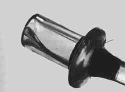
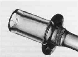
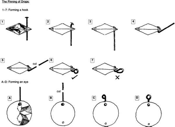
7.5 THE PINS AND PINNINGThroughout the late 18th century and most of the 19th century, the linking pins for drops were made of drawn copper wire. Over the years, stress corrosion occurs and causes embrittlement, which makes the pins weakened and fragile. Copper pinning wire was originally used in a soft (annealed) state, and, as a result, period pins have frequently become distorted. Attempts to straighten them will usually cause them to break. Pins in brittle, aged condition should be removed and replaced with newly made brass chandelier pins. In the replacement of original pins, restoration is much more important than conservation. The new pins are made from a malleable alloy, but they are stronger than the traditional copper ones. They are also available for use in continental chandeliers with tin plating. It is usually safe, working slowly and carefully, to cut away the old pins. It is sometimes necessary to straighten them before removal so that the cutters used to remove them can be safely kept away from the surfaces of the glass drops. Cutters can easily force a conchoidal flake of glass off the surfaces of the glass drops. Faced with an enormous number of pins to remove or a jumble of tangled drops, the dressings can be immersed in a bath of dilute nitric acid to dissolve the old pin material. This bath will not harm the glass, but it is extremely hazardous and should be used with extreme caution. Any previous repairs to the glass parts will also dissolve in the acid bath, so care must be taken to collect and support any detached pieces. Dissolving the pins rather than cutting each one out may prevent the creation of many small flake losses on the edges of the drops surrounding the pin holes by the pressure from the pliers. After the old pins have been removed, the next step is to make a pattern for each set or chain of dressings required. The following tips will help in determining the proper organization of the sets. Chains and swags are almost always graded by size, with the larger drops to the bottom. In a swag composed of pear-shaped drops, the direction of the drop changes orientation on either side of the center drop, which should be oval. The pins should be properly aligned to allow the drops to hang freely and in plane with the swag or chain. Correct assembly of swags for neoclassical chandeliers requires that they should be permanently fixed at their right As described, swags or festoons are made up of several sizes of drops, small at the ends and larger at the center. The vertical drops, too, grade from small to large as they fall. It is best to set out groupings of the sized drops that will be required to make each set of dressings. There are seldom enough drops of each size needed. Additional drops may have to be found from a suitable supplier, such as a reputable lighting device dealer, or reproduced as discussed in section 7.8. Only when all the necessary sized and shaped drops are at hand should the repinning begin. Drops are generally hung with their flat, cut, or pressed side to the outside to better catch and reflect the available light. 7.6 REPINNING DROPSAll that is required to repin a chandelier is a supply of suitable pins and a pair of needle-nosed, side-cutting pliers (see section 5). To form a hook (fig. 13, 1–7):
To form an eye (fig. 13, A–D):
7.7 RESETTING THE ARMSIf the filling plaster holding glass and metal mounts together is weakened, cracked, or damaged, all the mounts should be removed. The plaster can be removed by soaking the mount ends in water for several days. The plaster will begin to soften after a few days. If the water is warm, the plaster may soften more rapidly. As much of the plaster as possible should be mechanically removed with small hand tools. Then, holding the mount with pliers that have been adequately padded so as not to bite into the brass, move the glass arm or nozzle or other element rapidly but gently, side to side. Usually the mount will come away fairly easily. If the plaster has not been sufficiently softened or weakened, patience is required, and the rapid reciprocating movement should be repeated Often an amateur or a previous restorer has tried to fit an arm into the wrong socket, ignorant that both are marked. If the arm mount is found to be too big, the temptation is to reach for a file and open up the hole in the arm plate, only to find the next hole too big for all the remaining mounts. If the mounts or the holes in the arm plate have been altered, employ a competent metalworker to make adjustments for previous alterations, including the requisite renumbering if necessary. Resetting the arms in their mounts requires that the central support rod be secured in a bench vise so that the arm plate is well above the level of the vise. The rod must be vertically oriented. Fit the arm mounts into the sockets and press them securely in place. If any are loose, apply a tough rubber band or padded clamp around their lower ends, below the arm plate, to temporarily take up any slack that would allow them to tilt or allow the arms to fall out of alignment once they are reinserted into their mounts and unsupported after setting. Each arm will need a block on which to rest while plaster is added to each mount and allowed to set. Ideally, there should be room to set all the arms in place at the same time, but Mix the replacement plaster to the consistency of thick cream, fill one mount, press one arm into position, check it for horizontal and vertical alignment, wipe away most of the surplus plaster, check again, and leave it for 10 minutes. Repeat for the remainder of the arms. When all have set, remove the arms with affixed mounts and pare away any excess plaster with a knife, leaving a neat, flat surface level with the lip of the mount. At this point, remove the rod from the vise, attach it to the shackle, and rehang it. Then replace the arms. It is necessary to set the arms with the rod fixed in a vise because the arms require immobile support that cannot readily be given when the rod is freely hanging. Since a chandelier normally hangs free, further setting of the plaster should take place with the rod hanging so that variations in the weight of the arms can allow the chandelier to settle to its natural level. In the case of a chandelier with detachable nozzles, set the mounts with the arms and pan platforms first. But before beginning this step, check the nozzle mounts for fit and associated numbers and screw or push them into their positions. Plug the open end of the arm mount within the pan platform with sufficient cotton or other barrier material so that the plaster cannot meet the underside of the nozzle mount and adhere to it. Ideally the numbers on the mounts on both ends of each arm, the arm plate, and the nozzle mount should correspond to each other. Place all the mounts loosely in position on the ends of the arms. Mix the plaster and set the mounts in position, working in pairs opposite each other and constantly checking that they are horizontal from all directions. Next, place all the nozzles in position on the mounts just set. This step is necessary, as it was with the arm mounts, to keep the balance of the chandelier. Place one nozzle in its position and the rod swings out of the vertical; place all of them in position, and the chandelier finds its correct level. It is sometimes possible to place the nozzles upside down on their mounts in the interest of safety. The important thing is to distribute the weight of the nozzles evenly in the right places. Mix the plaster and set the nozzles, working in pairs opposite each other as before and checking for horizontal alignment even more carefully. When dry, surplus plaster can be cut away; a final stiff brushing will remove all the excess. 7.8 REPLACING MISSING PARTSWhen parts of a chandelier are missing, the first course of action is to decide whether they should be replaced. The typical life of a chandelier involves much arrangement and rearrangement of parts. When elements are broken they may be replaced with new or different parts. As styles changed, chandeliers were often refitted and modernized rather than replaced. It is often impossible to know what a chandelier looked like at any particular moment in its history. The best choice may be a close representation of what a chandelier could have looked like at a particular time. Once the time period is chosen, a scholar of glass lighting devices can help determine which pieces are inappropriate and which may be missing or need to be replaced. Chandeliers were often originally assembled of parts from different sources, so the use of unoriginal, period replacement parts is not as problematic as it may be with other types of collection objects. If period replacement parts are deemed appropriate, a good chandelier or lighting device dealer may be able to locate suitable pieces. The dealer will require measurements and a sketch of the parts needed. If it is not possible or desirable to use period replacement parts, the missing pieces can be fabricated out of new glass, metal, or synthetic resins. Metal and glass parts can be cast from molds taken from duplicate original pieces on the object. Decorative elements can be cast and electrotyped or painted (for metal parts) and cast in epoxy and polished (for glass parts). If the pieces to be replaced cannot be molded and cast due to complex orientations or deep undercuts or due to the need for maximum structural strength, the pieces can be refabricated by an experienced glassworker or metalworker. Again, measurements, photographs, and sketches are needed for this process. Losses to existing parts can be cast in epoxy resin from silicone rubber or wax molds taken from existing portions of similar parts. Epoxy resins of suitable refractive index make excellent fill materials for the repair and filling of chandelier pieces (figs. 14, 15). Parts that are entirely lost but are represented by duplicate original pieces can be reproduced by taking molds of remaining parts, duplicating them in epoxy resin, and altering them cosmetically to match. The technical discussion of the fabrication of missing parts is beyond the scope of this article. For more information see Larsen (1981) and Newton and Davison (1989). 7.9 ELECTRIC LIGHTING AND CHANDELIERSMany chandeliers and other lighting devices have been wired for electricity with added imitation candles and/or electric lamps. The electrification of important glass fixtures is an unfortunate reality today. Period lighting devices were not originally designed or built to accommodate wires and lamp housings. The introduction of wiring to chandeliers often causes damage to both glass and metal parts. Holes are often drilled into parts, resulting in weakened structures and visible intrusions. Wires are forced into spaces too small to accommodate them, causing cracks and breaks to the object and damage and wear to the wiring. Wires are often glued, wired, soldered, or twisted along structural members. Lighting devices are sometimes wired with small-gauge wire that is frequently below current electrical code standards. Smaller wire was used in an effort to hide the wiring and to fit it through small spaces not initially intended for wire. The wiring on many devices is old and has not withstood the repeated movement, adjustment, cleaning, and handling that these devices are subject to in the home or the museum. Electrical shorts in the wiring are common, caused by exposed metal wires and uninsulated connections on the lighting device. Aside from the physical problems of electrified period lighting fixtures are the interpretive problems. Accurate light levels and ambiance are not achieved when artificial electrical elements Although electrification is extremely damaging to chandeliers, it is not always possible to avoid it. Many chandeliers are already wired and are used by their owners for primary room lighting. Greater care is needed for any activities involving wired lighting fixtures. Make sure the power supply has been interrupted and the object has been disconnected before beginning any operations. If a chandelier must be electrified, the wiring should be performed by a team consisting of a conservator or collection technician and a bonded electrician. Creative solutions will be needed to solve a variety of difficulties in wiring a chandelier, not the least of which is the fact that a chandelier can only be partially assembled before it is hung. Final wiring and assembly will need to be done in situ and should comply with all electrical codes. Low-voltage wiring can be an alternative that requires smaller-sized wires and lamps that produce less heat during operation. |