THE CARE AND CONSERVATION OF GLASS CHANDELIERSJULIE A. REILLY, & MARTIN MORTIMER
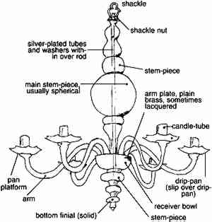
ABSTRACT—Glass chandeliers are large, complex, and fragile. They are a challenge to conserve and care for properly. This article will help provide some of the technical, specialized information needed to make chandelier conservation and care easier and safer. Terminology, history, stylistic development, safe handling, disassembly, reassembly, conservation, and restoration techniques for glass chandeliers are discussed. TITRE—L'entretien et la conservation des lustres en verre. R�SUM�—Les lustres en verre sont des objets de grandes dimensions, complexes et fragiles, difficiles � conserver et entretenir convenablement. Le pr�sent article fournit quelques informations techniques qui aideront � faciliter la bonne conservation et l'entretien de ces lustres tout en r�duisant les risques. Terminologie, histoire, d�veloppement stylistique, maniement appropri�, d�montage, remontage, conservation, et techniques de restauration pour les lustres en verre sont pr�sent�s. TITULO—El cuidado y la conservaci�n de ara�as (candeleros colgantes) de vidrio. RESUMEN—Las ara�as (candeleros colgantes) de vidrio son grandes, complejas y fr�giles. Representan un desaf�o para conservar y mantener. Este art�culo ofrece alguna informaci�n especializada y t�cnica, necesaria para que sea m�s f�cil y segura la conservaci�n y el cuidado de las ara�as de vidrio. Adem�s se discutir� la terminolog�a, historia, desarrollo estil�stico, manipulaci�n segura, desmontaje, montaje, conservaci�n y t�cnicas de restauraci�n de ara�as de vidrio. 1 INTRODUCTIONThis article will cover the basic information required for conservators and other museum professionals to work safely and successfully with glass chandeliers for the purpose of routine maintenance, installation, storage, conservation, and restoration. The topics addressed include a definition of the glass chandelier; terms needed to define and compare the various parts of the chandelier, a brief history of the structure and style of early glass chandeliers, and the care, handling, disassembly, conservation, and restoration of glass chandeliers. Glass chandeliers require approaches and procedures for care that are different from those for metal or metal and glass lighting devices, although many of the issues discussed in this article will be helpful to anyone working with devices decorated with glass elements. 2 THE GLASS CHANDELIERLittle of a practical nature has been published on the subject of glass chandeliers (Davison 1988). Indeed, there is little written that accurately describes the evolution of the glass chandelier (Mortimer 1987). There is so little in print about the glass chandelier that this article and a detailed book currently in preparation by Mortimer will add significantly to the body of available information in print. From the mid-17th century onward it was fashionable to embellish the metal framework of lighting fittings with glass or rock-crystal ornaments in the form of faceted beads, shaped pendants, and other styles. However, it was not until glassmakers first risked load-bearing glass arms that the true glass chandelier was born. This The following discussion focuses on the generic structure for glass chandeliers, from their inception around 1720 until the end of the 18th century. There were, of course, continued improvements and changes as time passed, but the general assemblage remained fairly consistent. Figure 1 is a basic diagram of a glass chandelier, labeled with the terms proper for an early glass chandelier. A detailed glossary of terms can be found at the end of this article. Some terminology may vary from country to country or as design elements are developed and employed.
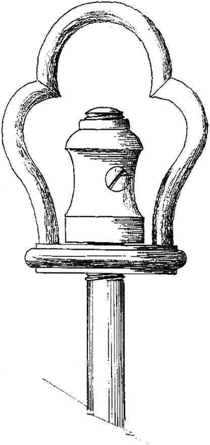
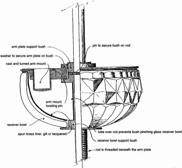
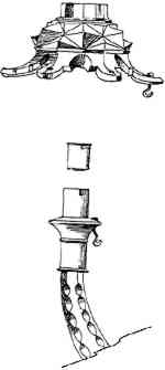
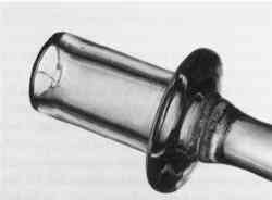
The elements found on the central stem of a chandelier, the stem-pieces, consisted of shaped glass forms arranged above and below a large central piece that was almost exclusively spherical (see fig. 1). The stem-pieces were supported on a metal rod that was, in earlier times, threaded along its entire length. One or two metal washers or bushings with conforming threads were positioned along the rod to take the weight of major stem-pieces and prevent their pressing too heavily on the stem-pieces below. A circular metal plate called the arm plate or receiving plate provided a console from which the arms emerged, each fitted with a cast square or turned round mount that fit into a unique matching hole in the arm plate. Corresponding mounts and holes were marked with pairs of matching letters or numbers to relate each mount to a specific hole. To hide the mechanical attachments on the underside of the arm plate, a glass receiver bowl was provided. The bowl was sometimes fitted with a spun metal liner or may have been gilded or silvered on the interior to further hide the mechanical fittings. The chandelier usually hung from a decorative suspension shackle, which was free to rotate 360�. The shackle was held on the support rod with a turned nut, which screwed onto the top of the metal rod and was prevented from unscrewing by a stop-screw inserted through the nut into the rod itself (fig. 2). The chandelier stem terminated with a glass finial, sometimes in
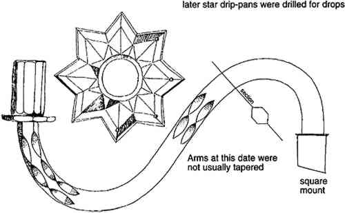
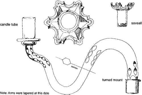
2.1 CANDLE RECEPTACLES AND ARMSThe first glass chandelier arms incorporated an integral drip-pan and candle-tube or nozzle. These elements were soon found to be impractical because a low-burning candle could crack the tube and perhaps even the pan. It would then make it necessary to replace the entire arm assembly, which would be difficult to match completely to the original. Thus, a detachable drip-pan came into use in 1730–35 and was made to slip over the integral candle-tube and rest on a glass platform provided for it (fig. 4). This construction continued until ca. 1780.
Meanwhile, continuing problems with lowburning candles cracking tubes resulted in the introduction of separate glass sconces or nozzles, also known as savealls, around 1760. These small, cup-shaped units had a built-in candle-tube that could be inserted into the existing tube affixed to an arm. The candle was placed in
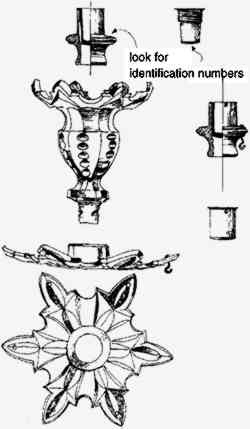
By 1780, however, following the neoclassical revolution in taste, completely detachable candle nozzles evolved (fig. 6). These nozzles were vase-shaped, with the upper border cut to an elaborate profile known as the Vandyck border. The name derived from the shaped borders of lace collars worn by many of the artist's sitters. The arm terminated in a turned metal female fitting with a surrounding platform for the drip-pan. The drip-pan center hole was now much smaller since it no longer had to pass over a tube of sufficient diameter to hold a candle. Into the terminal female socket was screwed, or socketed, a conforming mount onto which the candle nozzle was affixed.
2.2 ATTACHMENT OF THE ARMSThe method of securing the arms to the arm plate, discussed briefly above, underwent only one change in the 18th century. Before 1750, the mounts were square and required much hand-fitting. Later, turned round mounts were used. These mounts could be cast and finished on a lathe, as could their sockets in the arm plate, and then installed in the arm plate and on the ends of the arms. Turned mounts also had a further advantage in allowing the glass arms to swing slightly side to side if touched by a ladder
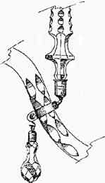
2.3 DECORATIONThe first chandeliers were plain. The stem-pieces were cut, often in flat planes. Occasionally they were molded, perhaps in a diamond mesh pattern. Arms were initially plain, but from about 1740 onward they were cut. The early cut arms appear to have been cut flat on each side, with long slices removed from the four resulting angled corners. Later, the arms were cut six-sided and then decorated with slices removed, as before. As the 18th century progressed, the slices 3 CHANGING STYLE AND THE GLASS CHANDELIERArchitectural styles were reflected in the progression of stylistic elements in chandelier design. The rococo style brought great elaboration to lighting devices, with double-curved arms and the addition of extra glass ornamentation in the 1760s. Separate decorative ornaments were introduced, such as spires (fig. 8) that could be affixed to the chandelier by mounts strapped to the arms (fig. 9). Other elements and drops were designed to hang singly from wires. Glass canopies were added to the central rod as stem-pieces in order to mount extra decoration that was hung from holes in the borders of the canopies (fig. 10).
The stems of neoclassical chandeliers (ca. 1775–1800) were arranged around a classical vase shape stem-piece. Chains of graded drops were draped symmetrically from the canopies and/or the arms, point to point, and linked by oval glass paterae drops (shown in fig. 12). Vertical prisms or spires of triangular section were added, normally mounted on small arms that alternated with those bearing candles. The prisms were initially notched like their contemporary arms or were, later, plain.
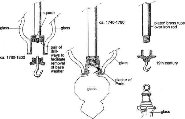
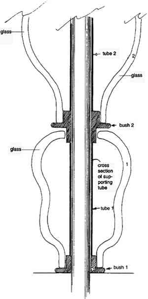
By the end of the 18th century, major changes were taking place in chandelier design, with metal frames gaining in popularity. These frames were dressed with cascading chains of graduated glass drops affixed at top and bottom. Glass stem-pieces thus became redundant, and the chains of drops themselves provided the form of the chandelier. From the main rim of such chandeliers, which have been termed “Regency” but which are more accurately called “frame” chandeliers, extended short arms of glass or metal that supported glass drip-pans and nozzles. The surface patterns and decoration of the drip-pans and nozzles developed in a 3.1 OTHER ORNAMENTATIONThe third quarter of the 18th century saw the greatest profusion of ornamentation before chandelier design fell under the influence of the neoclassical movement with its more limited design vocabulary. Most if not all of the elaborate and varied drops, pendant ornaments, and standing ornaments were cast into a basic shape before cutting. These ornaments included tall tapered prisms or spires. The variety of decoration on English chandeliers was, however, exceeded on the Continent, where the rococo style rose to even greater heights. There, pendant and standing ornaments were more frequently flat and often had patterns cast into one side. Elaborate floral or other elements were sometimes constructed with glass beads and wire. Unlike the English practice, continental spires The presence of flat drops with elaborate cut borders and wired beadwork ornaments is one of many indications of the probable continental source of a chandelier; however, one of the most secure indicators can be the variable fluorescence of different glass compositions under ultraviolet light. Virtually all 18th-century English chandeliers were of lead glass, and all continental chandeliers were of soda lime glass, which should exhibit differing colors of fluorescence when compared under ultraviolet light. As will be noted, ultraviolet light frequently also discloses incompatible replacements in a chandelier and can confirm the suitability or originality of some components. Above all, a knowledge of the evolution of chandelier design is essential for anyone who undertakes more than remedial efforts to return a chandelier to anything approaching its original state. 3.2 CONSTRUCTION OF THE SHAFTMaterials used in the construction of chandeliers (other than glass itself) varied little throughout the 18th and 19th centuries. The central rod was of iron, initially threaded along its entire length and later smooth with threading only where required for fitted bushings. Initially, the rods were wrapped in metal foil, perhaps tin, to give a silvery effect within the glass rather than the black of untreated iron. As the century advanced and supportive metal bushings to hold stem pieces were introduced, sleeves of silver-plated brass were substituted for the wrapped tin coverings. By the end of the 18th century, sufficient bushings or washers were included in the design to support the individual weight of most of the glass stem-pieces. This additional strength was achieved by providing a bushing with a turned rebate on its upper side to fit the hole in the bottom of the first glass stem-piece. A tube of a suitable diameter to be a snug fit over the iron suspension rod was cut and slid inside the first glass stem-piece. A second bushing was then turned whose lower rebate fit the hole in the top of the first glass stem-piece, and the tube was cut at a point that allowed that stem-piece to turn freely without obstruction from its associated metalwork. The top of the second bushing carried a rebate turned to fit the hole in the bottom of the second glass stem-piece, the weight of which was carried by the bushing supported on the tube within the first glass stem-piece (fig. 11).
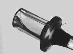
The above description is significant, because the essential principle followed in assembling the somewhat heavy components in an early-18th-century glass chandelier shaft was to allow the weight of each stem-piece to be independently supported by a bushing affixed to the rod. In the late 18th century, not all parts were so supported. For instance, it was common practice in a neoclassical chandelier to have a single tube within a group of minor (and thus lightweight) glass stem-pieces, with a bushing at the central vase or urn to provide support. When chandeliers with glass stems reappeared in the second half of the 19th century, it was typical to provide every glass stem-piece with its unique, numbered metalwork. The metalwork of a glass stem should always be numbered. The usual formula is to use numbers from the arm plate upward and letters from the arm plate downward. Numbers are normally stamped on the upper end of the stem tubes (not essential) and on the upper faces of the stem bushings (essential). Ideally, all metalwork should slide into position above the arm plate, with the possible exception of a final threaded fitting below the top shackle with its terminal nut and stop-screw. All washers or bushings supporting glass stem-pieces below the arm plate should be threaded. Thus, when assembling a chandelier, all of the upper parts of the stem are put together before hanging, and the lower parts are added singly, each held in proper place with a threaded washer or bushing. 4 EXAMINING CHANDELIERS4.1 A HANGING CHANDELIERIt is typical to examine a hanging chandelier from a ladder. Furniture and other objects should be removed so that they are protected from the movement of the ladder and from falling chandelier parts that may be loosened during examination. Also useful for an in situ examination on a ladder are an ultraviolet light and a tape recorder for recording notes while standing on the ladder. UV light, of both short and long wavelength, can be used to locate pieces of glass made of differing glass formulations and can often be used to indicate which pieces have been added or substituted on a chandelier. While examining a chandelier, it is best not to rotate the chandelier for access to the opposite arms. Many chandeliers are not hung from a shackle capable of rotating freely. Some hanging fixtures may actually become unscrewed during rotation, with unfortunate results. Take extra care with chandeliers and lighting devices that have been electrified. Substandard or subcode wiring is common. Wear and use often loosen electrical connections and lead to electrical shorts and fires. Good photographs and sketches should be prepared for chandeliers. They can prove invaluable during later research, writing, study, or comparisons of related pieces. They are essential for careful reassembly of chandeliers. 4.2 A DISASSEMBLED CHANDELIERWhen a chandelier is already disassembled, as may be the case for objects not currently on display or objects that have recently been shipped, examination is somewhat different. The order or sequence of the stem-pieces, for example, is not evident and may need to be hypothesized. Studying the edges of pieces that could potentially adjoin might be helpful. One must mentally assemble the chandelier to determine whether all the major pieces are present. UV light can be used to help separate parts of differing glass composition. Sketches are helpful. Surfaces and details that are normally not accessible for examination on a hanging chandelier can be examined and documented more thoroughly on disassembled pieces. On stem-pieces, scratched numbers or letters that may guide the order of assembly may be visible, although they may relate, confusingly, to their position in the shaft of an entirely different chandelier if the pieces have been taken from different objects. 5 HANDLING AND DISMANTLING GLASS CHANDELIERSWhen working on a chandelier in situ, clear adequate space beneath the object for ladder movement and for laying out parts that need to be removed. A moving blanket or other soft, firm padding should be placed on the floor. Several long work tables, also padded, can be useful. Other items that may be needed include a camera, a hand-held tape recorder, a variety of pliers, scissors, wire snips, chandelier pins, string, Ziploc polyethylene bags, paper hang tags for temporary labeling, a whisk brush, a notepad, pencils, and an assortment of hand tools. A sturdy ladder of appropriate height or scaffolding, securely assembled, is essential. Side-cutting, needle-nosed pliers or rosary pliers can be specially altered for chandelier pinning by shortening the needle tips on a grinder to increase the angle of the jaw cones. One may also prefer to grind the outer face of the side-cutter flat so that a flush cut can be made on the blank pins. Wearing gloves is not recommended. Fabric or plastic gloves will catch on protruding pins and other exposed metal fittings and may cause damage to the object. Working with a ladder or scaffolding or with an object as large as a chandelier always requires the presence of more than one person. Only staff that feel secure and comfortable working on a ladder or scaffolding should be asked to participate. If the object is suspended over an open area or stairwell, the area beneath the object should be cordoned off to keep staff and visitors from walking To dismantle a chandelier that has glass stem-pieces, arms, and chains of drops, first remove all the chains. As a rough guide, work from the outside inward and from the bottom upward. Take note as you go where each set of drops belongs, and keep the sets separated and labeled. Paper string tags are useful for temporarily labeling chains of drops. Ziploc polyethylene bags can also be used to label and separate parts and groups of parts. The pins holding the drops may be decayed, so be prepared for links to break. If the condition is particularly poor, be prepared for drops to fall as the dressings are removed. Groupings should be removed and kept in their specific arrangements (see sections 7.5 and 7.6). If the chandelier to be dismantled has detachable nozzles, remove them next after the dressings. The nozzles may be in threaded mounts or in socket mounts that can be removed without much twisting. Remove the drip-pans after the nozzles. Next remove the glass arms. Glass has a greater tensile strength than its reputation might suggest, but it will only stand so much torque or stress. Take great care when dealing with glass arms. To remove an arm from its socket, first feel its degree of movement by moving the outer end. See if it will swing sideways at all. Gently raise it to check if it is loose in its socket or a tight fit. If loose, hold the outer end in one hand and draw it out of the arm plate with the other hand, grasping it tightly and bearing the weight near the arm plate, using the outer hand only to gauge the degree of mobility and movement. Likewise, when adding load to a glass arm, always support the outer end of the arm as the load is transferred. It is dangerous to put a lamp bulb into an electrified fixture—particularly one with a bayonet fitting that requires combined downward pressure and a simultaneous twist. One can counteract the dangerous downward pressure needed by supporting the arm while the pressure is applied. Fortunately, this manner of fitting is not normally used in the United States. Early glass arms had square mounts that allowed virtually no lateral movement. Turned round mounts were an improvement. To ensure that the arms were inserted in the correct alignment equidistant one from another and in line across the arm plate, the fabricator attached a locating pin at the back of the mount. An answering notch was cut in the lip of the socket. On assembly, the arm mount should thus be pressed down so that the pin locates in the notch. If the chandelier shaft is in good condition, it should be possible to remove all the parts below the arm plate, one by one, before removing the shaft from the hanging apparatus. This is not always the case, however, and sometimes the entire shaft has to be lifted down and laid horizontally on suitable supports to be dismantled. Make sure that no weight is allowed to bear on the borders of the canopies, which are likely to be the stem pieces with the greatest diameter. After the chandelier is dismantled below the arm plate the shaft can be taken down and the parts above the arm plate can be removed, if needed. A specially designed chandelier cart with an A-frame on a rolling base can be extremely useful for moving and storing the assembled shaft of a chandelier. Better still, a chandelier destined for storage should be suitably labeled, completely disassembled, and properly packed. 6 DETERIORATION OF GLASS CHANDELIERSTwo hundred years or so after their manufacture, most chandeliers need work. Except for damage, the glass should be as sound as when it was made. The metal surfaces will have oxidized or discolored over time and may need attention. Many chandeliers are not installed properly and will need to be reinstalled. The chain that holds the chandelier must be made with steel or brass closed-link chain and should be adequate to hold more than the full weight of the chandelier. The ceiling hook should be securely fixed in such a manner that complete rotation of the chandelier cannot unscrew the hook or disturb its connection to the ceiling. For very high installations, a purpose-built winch with reduction gear and locking capabilities is desirable. It is best to have a qualified structural engineer determine the best method to fix the hook to the structure of the building. In the mid-18th century, chandeliers were often hung on counterpoises from a fixed hook. As the chandelier was drawn down by grasping the finial (screwed firmly to the bottom of the rod, as it would have been then), compensating counterweights rose up the chain. 7 CONSERVATION AND RESTORATION PRACTICESAs with all work with chemicals, solvents, and laboratory compounds, all materials selected for chandelier care and conservation must be used following the manufacturer's and occupational safety precautions. Personal protective equipment must be used as specified in the Materials Safety Data Sheets provided by law with all laboratory materials. Some chemicals discussed below, such as nitric acid and ammonia, are very dangerous and must be used following all of the manufacturer's safety recommendations. A materials and suppliers list follows. 7.1 CLEANING METALWORKMakers of the first chandeliers tended to tin-plate their brass mounts when they were within the glass and to gild or polish and lacquer them when they were outside the glass parts. About the middle of the 18th century, silver-plating was used, and by 1780 preference for gold inside and outside the glass was apparent. Silver-plated mounts were produced by a variety of methods, including fused, amalgam, close, French, and Sheffield plating. (For more information about silvering and silver-plating, see La Niece and Craddock 1993.) These mounts can be cleaned with a mild, custom-made dip solution or a slurry of precipitated calcium carbonate in ethanol and then coated to prevent tarnishing. Careful and complete coating with a cellulose nitrate or acrylic coating decreases the need for more frequent cleaning of the metal mounts and protects them from rapid corrosion or deterioration. Current research conducted under the direction of Chandra Reedy, funded by a grant from the National Center for Preservation Technology and Training, indicates that cellulose nitrate coatings may afford the best protection for metal objects in a museum environment (Reedy et al. 1998). We have found good practical success using a silver dip solution containing 3–5% (v/v) formic acid, 8% (w/v) thiourea, and 1/2% (v/v) photographic wetting agent in distilled water. It is essential to carefully rinse the dip solution from the metal mounts after dipping. Often the surface of silver cleaned with a dip solution remains very yellow after rinsing. Polishing will reduce the yellow appearance. (For more information about the cleaning of silver with dip solutions and precipitated calcium carbonate slurries, see For gold coverings, it is necessary to determine whether the mounts are in fact gold-plated or are lacquered with a tinted, spirit-shellac lacquer to imitate gilding. For actual gold-plating, a wash with a mild nonionic detergent solution will usually remove the dirt and reveal sound plating underneath. For spirit-shellac lacquer “gilding,” a lukewarm water wash with a soft brush followed by a wax coating may be all that is necessary. Occasionally, it is possible to clean badly soiled spirit-shellac imitation gilding with a dilute formic acid solution, but careful testing and great care are needed to prevent this cleaning method from removing deteriorated tinted shellac from the mounts. For an excellent review and discussion of the identification and treatment of spirit-shellac imitation gilding, see Long (forthcoming). Needless to say, one must completely understand the materials used to color or patinate metal surfaces before planning or beginning treatment. Even the mildest ammonia rinse or an excessively hot water wash will remove a spirit lacquer imitation gilt surface and/or blacken the underlying brass. Before proposing a treatment regime, one has to judge the condition of the metalwork, the materials and methods of fabrication, and the result desired. When new, a late-18th-century chandelier of high quality would have had brilliantly burnished gold-plate metalwork, which may still be present beneath 200 years of pollution and oxidation. As described earlier, the gilt appearance on the metal parts can also be achieved through the use of an imitative tinted shellac coating applied hot to the base metal surface. Retention of good surface appearance of the finish of the metalwork depends largely on atmospheric conditions. A chandelier hanging in a little-used historic house in the country will inevitably be in better shape than one in a big-city dwelling. The former will need infrequent cleaning, the latter, frequent, with the attendant handling dangers and wear. In addition, gas illumination used in the past produced an abundance of water vapor that had aggressive acids dissolved within. The acids have attacked the lacquer coatings and the metalwork beneath the gilt surface. The freshness and brilliance of the plating or the lacquer coating after treatment can sometimes be startling. Gold imitation lacquer can survive in good condition, but the lacquer itself will have deepened in color. Again, a knowledge of the development of design practices is essential in establishing the correct finish to metalwork on a specific chandelier. 7.2 CLEANING GLASSThe glass portions of the chandelier can be cleaned with a solution of equal parts of ethanol and distilled water with a few drops of ammonia added to increase the effectiveness of the cleaning solution. The pH of the cleaning solution should not be brought above 9 by the addition of the ammonia. Above a pH of 9 the solution can potentially dissolve the glass. (For a discussion of the dissolution of glass by alkaline aqueous solutions, see Newton and Davison 1989.) Available through chemical supply houses, pH test strips should be used to determine the pH before a batch of the cleaning solution is used. Wax deposits can be loosened with warm water and/or removed with aliphatic hydrocarbon solvents or acetone. 7.3 REPAIRING BROKEN METAL PARTSBroken metal parts that are not structural can be repaired with an adhesive such as an acrylic resin or a two-part epoxy resin. Structural repairs must be done using metalworking techniques such as soldering and brazing in order for the chandelier to remain safe. Only conservators experienced in these techniques should attempt them. Otherwise, a skilled metalworker can complete metalwork repairs working in conjunction with the conservator. As discussed earlier, 7.4 REPAIRING BROKEN GLASSBroken glass parts can be repaired by the careful application of acrylic or two-part epoxy adhesives to the break edges. The adhesive should be selected based on the strength of the repair needed, the dynamics and configuration of the break area, the setting time of the adhesive, and the index of refraction of the glass being repaired. There are a number of different adhesives routinely used in glass repair (Tennent 1979; Tennent and Townsend 1984a, 1984b; Newton and Davison 1989). The edges of broken parts should be cleaned of all extraneous material using solvents, cotton swabs, or hand tools such as a scalpel, if needed. The parts should be aligned and secured in place with very thin strips of clear tape or dots of cyanoacrylate adhesive. The adhesive chosen for the repair, preferably a professional-quality, optically matched formulation, should be fed into the break to fill all the voids and replace all air pockets. The repair should be left untouched until the adhesive has set enough to safely remove the excess (figs. 14, 15). Nonstructural repairs or those to parts or areas that do not bear or support a great deal of weight can be done with acrylic adhesives.
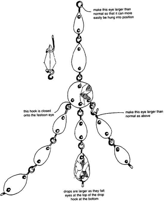
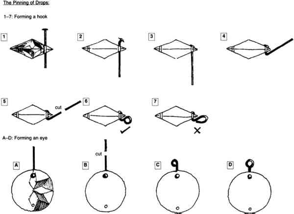
7.5 THE PINS AND PINNINGThroughout the late 18th century and most of the 19th century, the linking pins for drops were made of drawn copper wire. Over the years, stress corrosion occurs and causes embrittlement, which makes the pins weakened and fragile. Copper pinning wire was originally used in a soft (annealed) state, and, as a result, period pins have frequently become distorted. Attempts to straighten them will usually cause them to break. Pins in brittle, aged condition should be removed and replaced with newly made brass chandelier pins. In the replacement of original pins, restoration is much more important than conservation. The new pins are made from a malleable alloy, but they are stronger than the traditional copper ones. They are also available for use in continental chandeliers with tin plating. It is usually safe, working slowly and carefully, to cut away the old pins. It is sometimes necessary to straighten them before removal so that the cutters used to remove them can be safely kept away from the surfaces of the glass drops. Cutters can easily force a conchoidal flake of glass off the surfaces of the glass drops. Faced with an enormous number of pins to remove or a jumble of tangled drops, the dressings can be immersed in a bath of dilute nitric acid to dissolve the old pin material. This bath will not harm the glass, but it is extremely hazardous and should be used with extreme caution. Any previous repairs to the glass parts will also dissolve in the acid bath, so care must be taken to collect and support any detached pieces. Dissolving the pins rather than cutting each one out may prevent the creation of many small flake losses on the edges of the drops surrounding the pin holes by the pressure from the pliers. After the old pins have been removed, the next step is to make a pattern for each set or chain of dressings required. The following tips will help in determining the proper organization of the sets. Chains and swags are almost always graded by size, with the larger drops to the bottom. In a swag composed of pear-shaped drops, the direction of the drop changes orientation on either side of the center drop, which should be oval. The pins should be properly aligned to allow the drops to hang freely and in plane with the swag or chain. Correct assembly of swags for neoclassical chandeliers requires that they should be permanently fixed at their right As described, swags or festoons are made up of several sizes of drops, small at the ends and larger at the center. The vertical drops, too, grade from small to large as they fall. It is best to set out groupings of the sized drops that will be required to make each set of dressings. There are seldom enough drops of each size needed. Additional drops may have to be found from a suitable supplier, such as a reputable lighting device dealer, or reproduced as discussed in section 7.8. Only when all the necessary sized and shaped drops are at hand should the repinning begin. Drops are generally hung with their flat, cut, or pressed side to the outside to better catch and reflect the available light. 7.6 REPINNING DROPSAll that is required to repin a chandelier is a supply of suitable pins and a pair of needle-nosed, side-cutting pliers (see section 5). To form a hook (fig. 13, 1–7):
To form an eye (fig. 13, A–D):
7.7 RESETTING THE ARMSIf the filling plaster holding glass and metal mounts together is weakened, cracked, or damaged, all the mounts should be removed. The plaster can be removed by soaking the mount ends in water for several days. The plaster will begin to soften after a few days. If the water is warm, the plaster may soften more rapidly. As much of the plaster as possible should be mechanically removed with small hand tools. Then, holding the mount with pliers that have been adequately padded so as not to bite into the brass, move the glass arm or nozzle or other element rapidly but gently, side to side. Usually the mount will come away fairly easily. If the plaster has not been sufficiently softened or weakened, patience is required, and the rapid reciprocating movement should be repeated Often an amateur or a previous restorer has tried to fit an arm into the wrong socket, ignorant that both are marked. If the arm mount is found to be too big, the temptation is to reach for a file and open up the hole in the arm plate, only to find the next hole too big for all the remaining mounts. If the mounts or the holes in the arm plate have been altered, employ a competent metalworker to make adjustments for previous alterations, including the requisite renumbering if necessary. Resetting the arms in their mounts requires that the central support rod be secured in a bench vise so that the arm plate is well above the level of the vise. The rod must be vertically oriented. Fit the arm mounts into the sockets and press them securely in place. If any are loose, apply a tough rubber band or padded clamp around their lower ends, below the arm plate, to temporarily take up any slack that would allow them to tilt or allow the arms to fall out of alignment once they are reinserted into their mounts and unsupported after setting. Each arm will need a block on which to rest while plaster is added to each mount and allowed to set. Ideally, there should be room to set all the arms in place at the same time, but Mix the replacement plaster to the consistency of thick cream, fill one mount, press one arm into position, check it for horizontal and vertical alignment, wipe away most of the surplus plaster, check again, and leave it for 10 minutes. Repeat for the remainder of the arms. When all have set, remove the arms with affixed mounts and pare away any excess plaster with a knife, leaving a neat, flat surface level with the lip of the mount. At this point, remove the rod from the vise, attach it to the shackle, and rehang it. Then replace the arms. It is necessary to set the arms with the rod fixed in a vise because the arms require immobile support that cannot readily be given when the rod is freely hanging. Since a chandelier normally hangs free, further setting of the plaster should take place with the rod hanging so that variations in the weight of the arms can allow the chandelier to settle to its natural level. In the case of a chandelier with detachable nozzles, set the mounts with the arms and pan platforms first. But before beginning this step, check the nozzle mounts for fit and associated numbers and screw or push them into their positions. Plug the open end of the arm mount within the pan platform with sufficient cotton or other barrier material so that the plaster cannot meet the underside of the nozzle mount and adhere to it. Ideally the numbers on the mounts on both ends of each arm, the arm plate, and the nozzle mount should correspond to each other. Place all the mounts loosely in position on the ends of the arms. Mix the plaster and set the mounts in position, working in pairs opposite each other and constantly checking that they are horizontal from all directions. Next, place all the nozzles in position on the mounts just set. This step is necessary, as it was with the arm mounts, to keep the balance of the chandelier. Place one nozzle in its position and the rod swings out of the vertical; place all of them in position, and the chandelier finds its correct level. It is sometimes possible to place the nozzles upside down on their mounts in the interest of safety. The important thing is to distribute the weight of the nozzles evenly in the right places. Mix the plaster and set the nozzles, working in pairs opposite each other as before and checking for horizontal alignment even more carefully. When dry, surplus plaster can be cut away; a final stiff brushing will remove all the excess. 7.8 REPLACING MISSING PARTSWhen parts of a chandelier are missing, the first course of action is to decide whether they should be replaced. The typical life of a chandelier involves much arrangement and rearrangement of parts. When elements are broken they may be replaced with new or different parts. As styles changed, chandeliers were often refitted and modernized rather than replaced. It is often impossible to know what a chandelier looked like at any particular moment in its history. The best choice may be a close representation of what a chandelier could have looked like at a particular time. Once the time period is chosen, a scholar of glass lighting devices can help determine which pieces are inappropriate and which may be missing or need to be replaced. Chandeliers were often originally assembled of parts from different sources, so the use of unoriginal, period replacement parts is not as problematic as it may be with other types of collection objects. If period replacement parts are deemed appropriate, a good chandelier or lighting device dealer may be able to locate suitable pieces. The dealer will require measurements and a sketch of the parts needed. If it is not possible or desirable to use period replacement parts, the missing pieces can be fabricated out of new glass, metal, or synthetic resins. Metal and glass parts can be cast from molds taken from duplicate original pieces on the object. Decorative elements can be cast and electrotyped or painted (for metal parts) and cast in epoxy and polished (for glass parts). If the pieces to be replaced cannot be molded and cast due to complex orientations or deep undercuts or due to the need for maximum structural strength, the pieces can be refabricated by an experienced glassworker or metalworker. Again, measurements, photographs, and sketches are needed for this process. Losses to existing parts can be cast in epoxy resin from silicone rubber or wax molds taken from existing portions of similar parts. Epoxy resins of suitable refractive index make excellent fill materials for the repair and filling of chandelier pieces (figs. 14, 15). Parts that are entirely lost but are represented by duplicate original pieces can be reproduced by taking molds of remaining parts, duplicating them in epoxy resin, and altering them cosmetically to match. The technical discussion of the fabrication of missing parts is beyond the scope of this article. For more information see Larsen (1981) and Newton and Davison (1989). 7.9 ELECTRIC LIGHTING AND CHANDELIERSMany chandeliers and other lighting devices have been wired for electricity with added imitation candles and/or electric lamps. The electrification of important glass fixtures is an unfortunate reality today. Period lighting devices were not originally designed or built to accommodate wires and lamp housings. The introduction of wiring to chandeliers often causes damage to both glass and metal parts. Holes are often drilled into parts, resulting in weakened structures and visible intrusions. Wires are forced into spaces too small to accommodate them, causing cracks and breaks to the object and damage and wear to the wiring. Wires are often glued, wired, soldered, or twisted along structural members. Lighting devices are sometimes wired with small-gauge wire that is frequently below current electrical code standards. Smaller wire was used in an effort to hide the wiring and to fit it through small spaces not initially intended for wire. The wiring on many devices is old and has not withstood the repeated movement, adjustment, cleaning, and handling that these devices are subject to in the home or the museum. Electrical shorts in the wiring are common, caused by exposed metal wires and uninsulated connections on the lighting device. Aside from the physical problems of electrified period lighting fixtures are the interpretive problems. Accurate light levels and ambiance are not achieved when artificial electrical elements Although electrification is extremely damaging to chandeliers, it is not always possible to avoid it. Many chandeliers are already wired and are used by their owners for primary room lighting. Greater care is needed for any activities involving wired lighting fixtures. Make sure the power supply has been interrupted and the object has been disconnected before beginning any operations. If a chandelier must be electrified, the wiring should be performed by a team consisting of a conservator or collection technician and a bonded electrician. Creative solutions will be needed to solve a variety of difficulties in wiring a chandelier, not the least of which is the fact that a chandelier can only be partially assembled before it is hung. Final wiring and assembly will need to be done in situ and should comply with all electrical codes. Low-voltage wiring can be an alternative that requires smaller-sized wires and lamps that produce less heat during operation. 8 PREVENTIVE CONSERVATIONThe most fundamental factor in preventive conservation for chandeliers is proper installation. As discussed earlier, the right weight and type of chain must be used with an appropriate ceiling hook. The chandelier must be level and must make use of washers and bushings to safely distribute the weight of the stem-pieces on the support rod. Thought must be given to how the chandelier will be accessed for routine maintenance and cleaning. If real wax candles are to be used, the safety of routine maintenance practices will become critical to the long-term condition of the object. If the chandelier is electrified it should be examined regularly for its electrical safety. It is important to document the chandelier properly with written notes, sketches, and record photography. Any extra parts or parts that were not replaced on the chandelier during installation must be kept clearly labeled in a location where they will not be discarded, lost, or confused with any other parts or objects. Chandeliers may have associated chain covers of fabric or other passementerie that should also be retained for future reference or replication, if not suitable for installation. 9 CONCLUSIONSA well-assembled, clean, properly hung (unwired) glass chandelier can be breathtaking in its simplicity or in its elaborate ostentation. Suitable care and maintenance of these large, heavy, and extremely complex objects is difficult, but very rewarding. We hope that this article will encourage conservators to help owners, collectors, and cultural institutions to undertake the proper care of the chandeliers and other lighting devices in their custody. ACKNOWLEDGEMENTSAll drawings are by Martin Mortimer. The slides are courtesy of the H. F. DuPont Winterthur Museum and Gardens. APPENDIX1GLOSSARY OF TERMSARM: A variably shaped glass branch appended to the stem of a chandelier for the support of a candle or glass ornament (figs. 1, 4, 5). Also called a branch. ARM MOUNT: A metal fitting used to affix the arm to ARM PLATE: The cast and turned brass plate that accepts the arms of a chandelier. Also called the console or receiver plate(figs. 1, 7). BEAD: A faceted glass item drilled to receive a wire, usually spherical, but sometimes ovoid or other shape. BODY: The assembled central structure of glass stem-pieces and their interior metal supports. Also called the stem. BOBECHE: An American or French term for a drip-pan. BUSHING: The thick metal washer that centralizes and locates a stem-piece on the metal support rod. The washer or bushing is turned to provide two different-diameter collars and a flat lip upon which an upper stem-piece may rest. The lower diameter is turned to fit into the top of the neighboring stem-piece. Bushings are usually made of plated brass (see figs. 7, 11). CANDLE TUBE: The tubular outer part of a glass arm that holds the candle. CANOPY: Shaped inverted glass bowls with shaped borders, often provided at the top and bottom of a chandelier stem. Hanging from the outer margins various drops or chains could enrich the overall appearance of the chandelier (see fig. 10). CHAINS: A number of faceted glass drops linked by metal chandelier pins. The drops are sometimes graded in size (see figs. 12, 13). CONSOLE: Same as arm plate. DOUBLE CURVE: Some arms are shaped into a double S–shaped series of curves, particularly in the rococo period of the 1760s and 1770s (see fig. 5). DRIP-PAN: A glass dish encircling a candle tube or beneath a nozzle to catch falling wax drips (see figs. 1, 4, 5, 6). Also called a grease-pan. DROP: The glass element hung from various parts of a chandelier or strung with pins to form chains for decorative purposes. Also called a pendant. FERRULE: Same as arm mount. FINIAL: The normally solid glass terminal at the bottom of a chandelier. The bottom of the finial is usually the lowest point of a chandelier (see figs. 1, 3). Sometimes in the shape of a knop. GREASE-PAN: Same as drip-pan. KICK ARM: A secondary arm that normally alternates with arms bearing candles and rises above them. The kick arm usually carries spires, but sometimes candles. LINER: A spun brass bowl, gilded or lacquered, sometimes provided to lie within the glass receiver bowl to obscure the underside of the arm plate and its arm mounts (see fig. 7). NOTCHING: Decorative slices cut from the angles of various glass components; notably from arms and spires (see figs. 4, 5, 8–10). NOZZLE: A detachable candle holder. See also saveall and sconce. ORNAMENT: Elaborate components added to the basic structure of chandeliers in the rococo period. They could hang or stand from metal mounts. PAN: Same as drip pan. PENDANT: Same as drop. PLATFORM: The flange provided beneath a candle tube on a glass arm to support a drip pan (see fig. 4). PRISM: A term preferred in the 18th century for a RECEIVER BOWL: The bowl-shaped glass stem-piece that covers the underside of the arm plate (see fig. 7). RECEIVER PLATE: Same as arm plate. ROCK CRYSTAL: The natural colorless quartz stone used to decorate metal chandeliers before glass was used. The term crystal is normally only applied to the natural stone and is not appropriate to use in the description of glass. ROD: The central metal support of a chandelier. Usually iron or copper alloy and sometimes covered with silver or white metal plate covers or paint to alter the color of the metal within the glass stem-pieces (see figs. 1, 7, 11). Also called a shaft. SAVEALL: A detachable glass candle sconce or nozzle, its saucer-shaped top integral with a tube that sockets into a candle tube on a glass arm (see figs. 5, 6). See also NOZZLE and SCONCE. SCONCE: A term for a detachable candle holder of glass, sometimes interchangeable with nozzle. In the first half of the 18th century, the term was used to describe a pier glass with candle arms. See also NOZZLE and SAVEALL. SHACKLE: The suspension ring of a chandelier, often elaborately shaped. It is secured by a nut, itself fitted with a stop screw designed to prevent the shackle nut from unscrewing, making the shackle free to turn 360� (see fig. 2). SHAFT: Same as rod. SINGLE CURVE: The normal shallow S shape of the glass chandelier arm (see fig. 4). SOCKET: Same as arm mount. SPIRE: A tapered ornament of triangular section sometimes cut with notches on the angles, sometimes fitted at the top with small canopies and finials. The spires are often fitted to glass arms with metal mounts (see figs. 8, 9, 10). See also PRISM. STEM: Same as body. STEM-PIECE: A hollow glass element of various shapes that is fitted over the rod or shaft (see figs. 1, 11). Often made in a baluster shape. VASE: The central glass stem-piece of a neoclassical chandelier. Made either in one or two pieces (a vase and a separate cover) (see figs. 1, 11). REFERENCESBarger, M. S., and T. T.Hill. 1988. Thiourea and ammonium thiosulfate treatments for the removal of “silvering” from aged negative material. Journal of Imaging Technology14(2):43–46. Davison, S.1988. Cut glass chandeliers: Dismantling, cleaning, recording, and restoring. In Preprints of the Contributions to the United Kingdom Institute for Conservation 30th Anniversary Conference. London: UKIC. 90–93. LaNiece, S., and P.Craddock. 1993. Metal plating and patination: Cultural, technical, and historical developments. Oxford: Butterworth-Heinemann. Larsen, E. B.1981. Moulding and casting of museum objects. Copenhagen: School of Conservation of the Royal Danish Art Academy. Long, D.Forthcoming. Cleaning false gilding: A case study. In Gilded metals, ed.T.Drayman-Weisser. London: Archetype. Maryon, H.1971. Metalwork and enameling. New York: Dover.
Mortimer, M.1987. The English glass chandelier. In International Ceramics and Glass Fair and Seminar Catalogue. 39–55. Newton, R., and S.Davison. 1989. Conservation of glass. Oxford: Butterworth-Heinemann. Reedy, C. L., R. A.Corbett, D. L.Long, R. E.Tatnall, and B. D.Krantz. 1998. Evaluation of three protective coatings for indoor silver artifacts. Final report submitted to National Center for Preservation Technology and Training, Grant Agreement No. MT-2255—NC-011. Tennent, N. H.1979. Clear and pigmented epoxy resins for stained glass conservation: Light ageing studies. Studies in Conservation24:153–64. Tennent, N. H., and J. H.Townsend. 1984a. Factors affecting the refractive index of epoxy resins. In ICOM Committee for Conservation preprints, 7th Triennial Meeting, Copenhagen. Paris: ICOM. 84.20.26–84.20.28. Tennent, N. H., and J. H.Townsend. 1984b. The significance of the refractive index of adhesives for glass repair. Adhesives and Consolidants (September):205–12. Wharton, G.1990. A comparative study of silver cleaning abrasives. Journal of the American Institute for Conservation29:13–31. FURTHER READINGBrill, R. H.1962. A note on the scientist's definition of glass. Journal of Glass Studies4:127–38. Charleston, R.1984. English glass and the glass used in England, ca. 400–1940. London: Allen and Unwin. Fisher, P.1992. HXTAL NYL-1, an epoxy resin for the conservation of glass. In Glass and Enamel Conservation, UKIC Occasional Papers11:6–9. London: UKIC. Leeds City Art Gallery and J.Rutherford. 1992. Country house lighting 1660–1890. Leeds, England: Leeds City Art Gallery. SOURCES OF MATERIALSBench vise, ladders, flashlight, clamps, hand toolsAvailable at hardware stores Closed steel or brass chain, wood blocks, rubber bands, string, Ziploc bags, moving pads, detergent, distilled water, plaster, plasticine, acetone, ethanol, aliphatic hydrocarbon solvent, cottonAvailable at hardware stores Ammonia, UV light (long- and short-wave), paper tags, pH strips, (Fisher, CMS, Thomas) Parafilm, thiourea, photographic wetting agent, formic acid, precipitated calcium carbonateAvailable at scientific supply companies Cellulose nitrate coatingAgate Lacquer Co., 11–13 43d Rd., Long Island, City, N.Y. 11101, (718) 784-0660 Chandelier pinsMidwest Lamp Parts, 3534 N. Spaulding Ave., Chicago, Ill. 60618, (773) 539-0628 Tape recorderAvailable at electronics stores Acrylic resin (for adhesives and for coatings), two-part epoxy, resins, etc.Available from conservation supply stores RECOMMENDED CHANDELIER AND PARTS SUPPLIERSThe reader should note that the following suppliers may have a selection of extra chandelier pieces that they may be reluctant to part with. These pieces may have been gathered for the purpose of finishing incomplete chandeliers in the supplier's collection rather than to sell to others.Pegrex Ltd., 113–126 New John St., Birmingham B64 LD, U.K., (0121) 359-6881 Various gauges of chandelier pins in various lengths, as well as pinning pliers with round points and side cutters.Nestle, Inc., 151 E. 57th St., New York, N.Y. 10022, (212) 755-0515, Biggest U.S. supplier of light fittings.Andrew Burne, 24 Parkway, London SW20 9HF, U.K., (0181) 540-4422, Serious period light fitting restorers with a large selection of parts.Delomosne & Son Ltd., Court Close, North Wraxall, Chippenham, Wiltshire SN14 7AD, U.K., (0122) 589-1505, (0122) 589-1907 (fax), Specialists in period English light fittings with a large selection of parts.David Fileman Antiques, “Squirrels”, Bayards, Steyning, Sussex BN4 3AA, U.K., (0190) 381-3229, Restorers of glass light fittings with a selection of parts.Danys Sargeant, 21 The Green, Westerham, Kent TN16 1HX, U.K., (0195) 956-2130, (0195) 956-1989 (fax), Restorers of glass light fittings with a selection of parts.Neil Wilkin, Unit 3, Wallbridge Business Park, Frome, Somerset BA11 5JY, U.K., (0137) 345-2574, (0137) 345-2574 (fax), A glass house where copies may be made. Cutting is done offsite.Blue Crystal, Unit 6, 21 Wren St., London WC1, U.K., (0171) 278-0142, Good glass cutters.Wilkinson PLC, 5 Catford Hill, London SE6 4NU, U.K., (0181) 314-1080, Offers a wide range of made and cut parts.AUTHOR INFORMATIONJULIE A. REILLY is the associate director and chief conservator for the Nebraska State Historical Society, where her responsibilities include the initial establishment and operation of the Gerald R. Ford Conservation Center, a new regional center in Omaha, Nebraska. She has been an objects conservator for 14 years, working and teaching at the National Museum of American History, Smithsonian Institution; Colonial MARTIN MORTIMER joined his business, Delomosne and Son Ltd., (founded in 1905) in 1948. The firm of dealers in varied ceramics had been handling glass lighting fittings since the early 1920s, and it was not long before he made this aspect of the firm's activities his main interest. Some hundreds of period English chandeliers, candelabra, wall brackets, and candlesticks have passed through the firm's hands, most requiring attention. The quantity and quality of the material have made possible great experience together with a considerable photographic archive. Martin Mortimer has written many articles on the subject of glass lighting, and a book is near completion. Address: Delomosne & Son Ltd., Court Close, North Wraxall, Chippenham, Wiltshire SN14 7AD, U.K.
 Section Index Section Index |
