LIGHT PIPING: A NEW LIGHTING SYSTEM FOR MUSEUM CASESCATHERINE SEASE
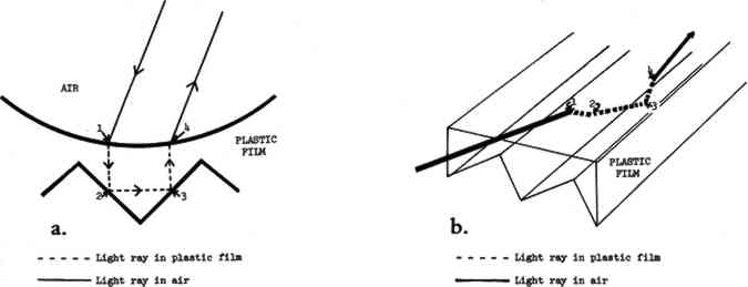
5 APPLICATION OF THE LIGHT PIPING ILLUMINATORSIt can be seen that the prismatic film has very efficient reflective and transmissive properties, depending on the angle at which light strikes the film. Both properties are utilized in the light piping illuminators to produce either a spot of light or an area source of light in the following manner. 5.1 POINT SOURCE OR SPOTLIGHTWhen used to make a spotlight, only the reflective property of the Optical Lighting Film is used. Light is simply transported down the length of the pipe by multiple TIR, that is, repeated total internal reflection. Light enters the pipe and strikes the smooth surface of the film. Some light is simply reflected there and continues to move down the pipe through the air. The remainder passes through the surface of the film with refraction and travels on to strike one of the prism surfaces (fig. 5a, b). As
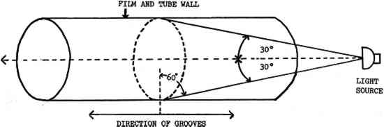
So that the light can pass through the pipe with a minimum number of surface reflections from the prismatic film and, hence, minimum attenuation, the rays from the source entering the end of the illuminator must strike the surface of the prismatic film at an angle of incidence of 60� or greater. Consequently, when rays are directed into the open end of the pipe from a point source on the pipe axis, those entering rays making an angle of 30� or less with that axis will be most efficiently transported through the illuminator. As is shown in figure 6, these rays will fall within a cone with the point source at its apex and a half-angle of 30�. For this reason, when creating a spotlight, it is important for the light source to utilize reflectors that will contain the beam of light to a cone with a half-angle of 30�.
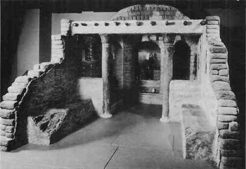
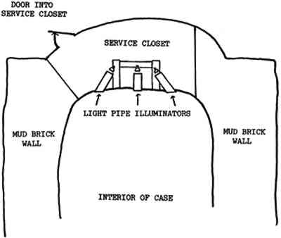
To use the light piping illuminator as a spotlight, the outer pipe is made of opaque white tubing to reduce light loss in the system through leakage. No extractor film is necessary. A disk of frosted Plexiglas can be attached to the far end of the pipe to soften the light beam as it leaves the pipe. Diffusers or lenses can also be placed at the end of the pipe to further control the quality of the light. As mentioned above, the light source should have as narrow a beam as possible so This application of light piping is used in a large case simulating a shrine to the Egyptian cat goddess Bastet (fig. 7). All spotlighting of objects in this case is achieved with light coming through the ends of pipes. The pipe illuminators in this case are made from 3 in diameter polyvinylchloride (PVC) tubing built into the ceiling of the case (fig. 8). Each tube extends downward through the ceiling into the case approximately 2 in. This end is closed off with a frosted diffuser adhered to the end of the tube and is blended into the ceiling of the case with the simulated mud mixture used throughout the interior of the case. The other end extends into the service closet on top of the shrine housing all the light fixtures. This end of the tube is covered with a disc of ultraviolet- absorbing Plexiglas adhered with a PVC glue. The light source for each pipe is a 50 or 75 watt narrow spot quartz lamp.
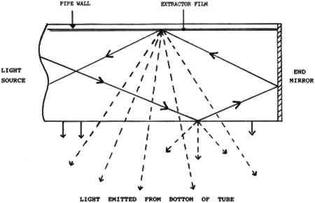
5.2 AREA SOURCES OF LIGHTOptical Lighting Film can also be used to extract light from the pipe anywhere along its length to create an area of light. This area of light is achieved by decreasing the angle of incidence of the light in the pipe with the prismatic film so that it is less than 30�. The ray is then transmitted efficiently through the film rather than being totally reflected by it. These rays are the ones that fall outside the cone in figure 6. This decrease in the angle of incidence enables light to be leaked, or extracted, from the pipe for illumination. Thus, by decreasing their angle of incidence to the prismatic film, it is possible to redirect rays being guided down the pipe. If this angle becomes less than 30�, rays will pass through the film and an opening in the plastic pipe. This angle change can be efficiently achieved with Scotchcal Series 7725 ElectroCut Film, a matte, white, highly reflective film. The Scotchcal film is made of a stable vinyl with a pressure-sensitive adhesive backing (3M 1988). When making the light piping illuminator, the extractor film is adhered to the smooth surface of the prismatic film before it is inserted into the pipe. By increasing the angle at which the ray hits the prismatic film, this film acts as an “extractor,” redirecting light rays and causing them to scatter at different angles, as shown in figure 9, roughly doubling the amount of transmitted, or leaked light (Saxe 1989). The addition of a mirror at the end of the pipe will serve to force light back down the pipe, increasing the light transmission
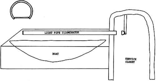
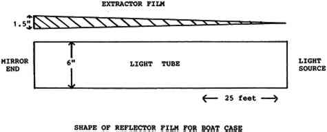
The shape of the extractor film will vary depending on the length of the pipe. For short pipes, the extractor film may not be needed or, if needed, may be only a thin strip. For longer pipes, the extractor film may equal the diameter of the pipe at the far end from the light source and taper down to a thin point near the light source. When opened out flat, the extractor film forms an isosceles triangle. This triangular shape is necessary for the optimum uniformity of light output (3M 1988). Light will diminish as it is transported down the length of the pipe. Therefore, at the far end, where there is relatively little light, a wide piece of extractor film is needed to transmit as much light as possible. At the light source end where there is plenty of light, little or no extractor is needed. To turn a pipe illuminator into a linear or area source of light, the pipe itself must first be modified. If the entire pipe is to be the light source, a tube of clear plastic is used. If only a portion of the pipe is to provide the light, an opaque tube is used with a clear window inserted in the desired place. A piece of Scotchcal Series 7725 ElectroCut Film is adhered to the smooth surface of the Optical Lighting Film before it is inserted into the pipe. A mirror, or mirror film, is affixed to the end of the pipe to reflect light back up the pipe to maintain maximum use of the light. In this application of light piping, both the reflective and the transmissive properties of the film are used. Light is transported down the pipe by reflection as described above. At the same time, the transmissive properties of the prismatic film, aided by the extractor film, allow light to be pushed out of the pipe along its length or through windows cut into the pipe. At Field Museum, the area source application of the piping system is used to illuminate a wooden boat from Pharaonic Egypt. This case is lit by a single pipe suspended below the ridge beam of the case (fig. 10). A single light source is located in a service closet in the simulated mud-brick arch to the right of the case. The light source is a 500 watt quartz bulb.
The pipe, made of opaque white PVC tubing, is 6 in in diameter and 300 in (25 ft) long. It is three-quarter round with a flat diffuser acting as a window adhered along the bottom surface. The prismatic film goes all around the inside of the pipe and has extractor film adhered to its smooth surface. This extractor film, shown schematically in figure 11 by hatching, is one-half the radius of the pipe at the mirrored end where there is little light, tapering to a point at the light source end.
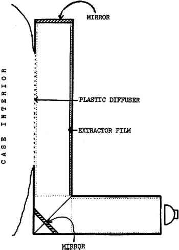
The light pipe for the boat case uses 45 sq ft of prismatic film at a cost of $135 (in 1988), less than the cost of the pipe itself. At the time of writing (1992), the cost of the film is $4–5 per sq ft depending on the quantity purchased. The same technique, but on a smaller scale, is used in conjunction with the light- bending feature to illuminate simulated burial niches. In these cases, almost the entire length of one pipe is actually built into the ceiling of the case. The window in the pipe consists of a frosted plastic diffuser that also serves as a window into the ceiling of the case through which the light enters the case (fig. 12). At the far end of this tube, a second pipe extends perpendicular to the first, forming a mitered corner. Where the two pipes join, a PVC mirror is positioned across the corner with PVC glue to form a 45� angle with the sides of each pipe. The light source is at the end of the second pipe. The light fixtures are located in a service closet behind the niches.
|