LIGHT PIPING: A NEW LIGHTING SYSTEM FOR MUSEUM CASESCATHERINE SEASE
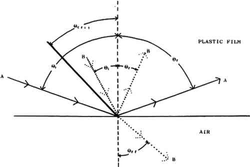
4 PRINCIPLE OF OPERATION4.1 TOTAL INTERNAL REFLECTION (TIR)Total internal reflection is the complete reflection of a ray of light within a medium from a surrounding surface back into that medium (Total internal reflection 1986). This phenomenon permits the efficient transportation of light in fiber optic cables and in light pipe illuminators. As illustrated in figure 2, when a light ray is incident on a boundary between two transparent media that have different refractive indices, a certain amount of light is reflected, with the angle of incidence equaling the angle of reflection. The remainder of the light is transmitted through the boundary with refraction of the ray. The angle of refraction is given by the well-known relationship, Snell's Law. TIR of a light ray incident on a boundary occurs only when the ray approaches the boundary in the medium of higher refractive index and its angle of incidence has a value greater than a certain critical value, called the critical angle. The value of the critical angle is determined by the refractive indices of the two media in contact at the boundary. In the case of the light pipe illuminator, one medium is air and the other is the plastic of the acrylic or polycarbonate Optical Lighting Film for which the critical angles are 42� and 39� respectively.
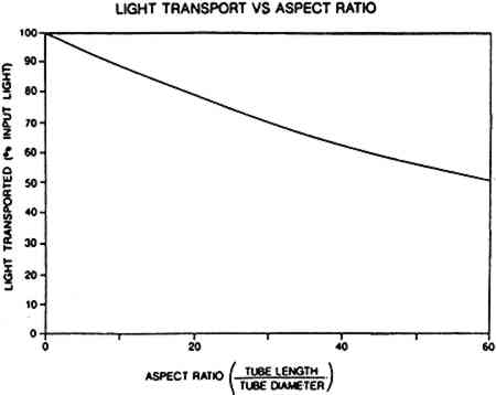
4.2 LIGHT FALL-OFFAlthough the efficiency of the prismatic film is high, there will be some light loss, approximately 30%, as the beam travels down the pipe. This loss is caused by slight microscopic imperfections in the prisms (Saxe et al. 1986). Figure 3 shows how light diminishes as it travels down a pipe and enables one to predict approximately the performance of a light piping illuminator. The aspect ratio on the horizontal axis is the ratio of the pipe length to its diameter:
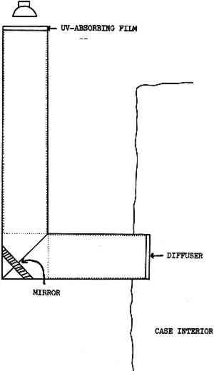
It is important to note that this is a ratio. Thus, the aspect ratio of a pipe 4 in diameter and 120 in (10 ft) long will be the same as that of a pipe 8 in in diameter and 240 in (20 ft) long. For both, the ratio is 30. This means that the light transport properties of both pipes will be the same. Thus, using the chart in figure 3, it can be determined that for these two pipes approximately 70% of It should be pointed out that this chart is only approximate. The actual efficiency of any given light piping illuminator will depend on the type of light source, extractor film, and reflector used and any alterations made to the pipe (3M 1988), which will be discussed below. To effectively transport and uniformly distribute light, the manufacturers calculate that the maximum aspect ratio is 40 to 1. Uniform distribution will be lessened at ratios higher than 40, but sometimes this effect can be counteracted by using a light source at both ends of the pipe. For pipes with aspect ratios less than 30, it is necessary to use an extractor film to distribute light evenly (3M 1988). 4.3 BENDING LIGHTAnother important feature of the light piping system is that it can direct light around corners as well as in a straight line. Bending can be achieved by positioning a mirror at the juncture of two pipes joined at an angle as shown in figure 4. Light enters one pipe and is transported by TIR down to the end, where it hits the mirror. The mirror redirects it into the second pipe, where it is transported down this pipe and comes out the end to illuminate the case.
4.4 TRANSMISSION OF ULTRAVIOLET LIGHTWhile no quantitative experiments have been reported on the transportation of ultraviolet light down a pipe, there are good reasons to believe that ultraviolet light will be selectively absorbed by piping. Both acrylic and polycarbonate absorb ultraviolet light, and the cumulative effect of light bouncing many times against the film as it moves down the tube should almost totally eliminate any wavelengths below approximately 380 nm (Saxe 1992). It stands Tests were undertaken at Field Museum to measure whether ultraviolet light is transported down a piping illuminator. A Crawford meter was used, which measures the ultraviolet content (UVC) of light in microwatts (μw) of ultraviolet light per lumen of visible light. The measurements showed that preferential absorption of the ultraviolet wavelengths occurred in the light pipe illuminator. The light source emitted light with a UVC of 150 μw/lumen. At the end of a 1 ft long illuminator, the UVC of the light was well below 50 μw/lumen. As the meter is not calibrated below 50 μw/ lumen, longer illuminators were not tested. Even though ultraviolet light levels with the illuminators are kept below the generally recommended level of 75 μw/lumen, all illuminators used at Field Museum are used in conjunction with ultraviolet-absorbing filters adhered to the light source end of the tube. Such a filter will also protect the degradation of the prismatic film itself over long exposure and is recommended when high ultraviolet-emitting light sources are used (Saxe 1992). |


