DIGITAL RADIOGRAPHY IN THE ANALYSIS OF PAINTINGS: A NEW AND PROMISING TECHNIQUEA. Everette James, S. Julian Gibbs, Malcolm Sloan, Ronald R. Price, & Jon J. Erickson
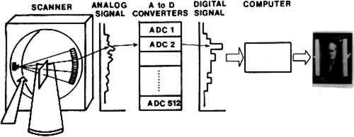
2 Scanned Projection RadiographyOne of the outgrowths of modern computed tomographic (CT or CAT) scanning instrumentation is a method for performing digital radiography which has many of the features of an ordinary radiographic study but in which each data point (“voxel” or small rectangular portion of the painting) is recorded in a discrete, finite manner.5 This technique is often called the “scout view.” At present, it is available in any hospital radiology department with computed tomography equipment. The method consists of placing the x-ray tube and detector assembly in such a position that the painting may be moved linearly through the x-ray beam (Fig. 3). As it is moved, data are collected by the computer from the detector array, and the image of the painting is thus stored in computer memory for subsequent manipulation and display.
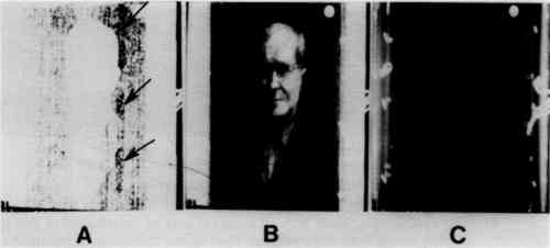
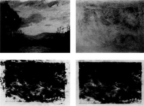
The collected image, with or without digital processing, is displayed on a video monitor. In this image, the intensity of each individual point (“pixel”) in the image is proportional to the quantity of x-rays passing through the corresponding point in the painting. The spatial resolution of this system is acceptable but not as good as that obtained by digital fluoroscopy. A major advantage of the scanned projection technique is that x-ray energies over a wide range may be used. This is possible because the electronics of the detector array can be optimized for the x-ray energy being employed. This calibration procedure is not available for either conventional radiography or digital fluoroscopy. Large fields-of-view are also possible (Figs. 4 and 5). The equipment is expensive ($800,000 to $1,200,000), but is widely available in major medical centers. We have had
The scanned projection images in Figures 4 and 5 demonstrate a second common technique of digital image processing known as “windowing.” Image intensity, or “brightness,” using this equipment is measured on an arbitrary scale in units called Hounsfield units (HU). For the typical machine, the dynamic range is −1024 to 1024 (or more) HU, where −1024 is assigned to the attenuation of air, 0 to water, and 1024 (or the equipment maximum) to the densest material in the subject. If the entire dynamic range of image intensity is displayed simultaneously, the contrast resolution is low, as in film radiography. However, the windowing technique allows the viewer to select only a portion of the dynamic range for display at any one time. For example, in Figure 5C, the window center is −445 HU, and its height is 61. That is, in this |