ENGINEERING PROPERTIES OF HISTORIC BRICK: VARIABILITY CONSIDERATIONS AS A FUNCTION OF STATIONARY VERSUS NONSTATIONARY KILN TYPESDEBRA F. LAEFER, JUSTIN BOGGS, & NICOLE COOPER
3 KILN TYPESDimensional and behavioral variability in brick can be considered a direct outcome of the firing process, which is highly dependent upon kiln type. Kilns have traditionally been distinguished by fuel type, efficiency and position of their heat source, heat distribution, and heat continuity. To demonstrate how the technology has changed along with the resulting products produced, examples of stationary periodic updraft and downdraft and stationary continuous draft kilns and their affiliate products are compared to nonstationary tunnel kilns, where the term “station-ary” reflects the position of the brick within the kiln. The major initial evolution is how the heat is distributed from a single source or group of sources across the kiln. The distribution begins as a localized and stationary process and eventually becomes not only relatively well distributed through the firing chamber but mobile between a series of firing chambers. The second and more important change in terms of engineering properties for brick is how in the 20th century the brick is changed from being a stationary element
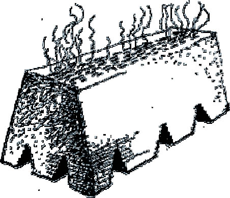
3.1 UPDRAFTUpdraft kilns date back to the ancient Greeks and have remained relatively unchanged in their basic features to the present (Rhodes 1981). Updraft kilns incorporate an enclosure in which to house the brick, lower apertures to insert fuel, and a chimney mechanism up above. A primitive but popular variant was the scove kiln, also known as a field kiln. Used extensively in the 18th century, with limited continued usage in the 20th (Conner 1910; Ritchie 1960), this temporary kiln was constructed out of raw brick that were fired as part of the overall process. Thus some of the brick that were fired were stacked to form the outside structure of the kiln (fig. 1), and some of the raw clay units were an inherent part of the firing apparatus (Rhodes 1981). The brick were placed in mounds, creating the appearance of a long rectangle with slightly slanted sides, and were strategically stacked to allow the flames and heat to access different sections of the mound via “passage-ways” (McKee 1973). The outer brick, prior to firing, were covered with a layer of clay and grass to allow venting of the vapors. In a single firing 40,000–50,000 brick could be fired.
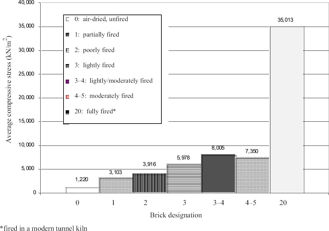
For scove kilns, initially brush, and then coal, was used as fuel (Rhodes 1981). The fires were fed and stoked for a week, and then the fire holes were covered with brick and mortar to prevent the heat from escaping. During this period the fires burned out, but the greater portion of the heat remained. While the kiln remained closed, the heat was allowed to dissipate for approximately one week. During the firing, brick were exposed to varying temperatures up to 982�C, resulting in very inconsistent strengths (Rhodes 1981). Brick close to the fires were overfired and sometimes vitrified, while brick far from the flames were softer and often more porous, causing them to be less desirable because of their lower strengths. Replication of historic material has also shown highly variable performance. Quarter-scale, extruded clay units were fired in a permanent, updraft kiln located in the University of Illinois Ceramics Engineering Department (Laefer 2001). The brick were dried for a minimum of 24 hours at 66�C. The units were fired in a stationary (porcelain) kiln with electrical heating elements on five sides (fig. 2). The brick were placed in two masses, each 464 mm by 597 mm by 127 mm high, containing approximately 1,400 brick per firing. Approximately 25,000 brick were fired in more than a dozen firings. Firing occurred at 496�C (verified by a no. 09 Orton cone) for at least 12 hours, with an additional day of kiln time for cooling. The goal was to create high-absorption, low-strength brick, typical of low firing. Since the power source was electrical (as opposed to gas or coal), the oxidizing (as opposed to reducing) atmosphere facilitated a rough correlation among coloration and brick absorption and strength, with the darker color being indicative of less absorptive and stronger brick; as the temperature increased, the iron oxide within the clay reacted and exhibited color change (tables 5, 6). Using a Munsell Color Chart, the brick were designated into categories and sorted according to color (see table 5). The designation numbers for the fired brick ranged from 1 to 5, with 1 being lightly fired and 5 most fired. The darker the brick, the less absorptive and stronger it was (see table 6). The designations were selected based on color distinctions that were consistently, visually identifiable by the student research assistants (Laefer 2001). During the sorting of the 25,000 miniature brick, many brick were found to have a bifurcation, where one half was of one designation and the other half another. Thus some brick are listed with a hyphenated number.
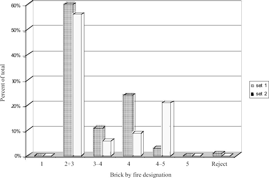
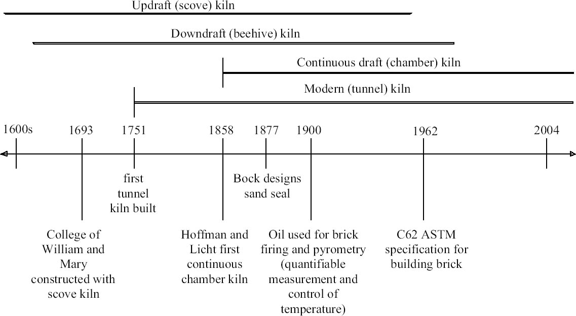
The results of two firings demonstrated the variability both within a single firing and between firings that will occur, even under highly controlled procedures using Orton cones and timed firings (fig. 3) (Laefer 2001); as this brick manufacturing was done for a larger research project with other objectives, the brick of designation 2 and 3 were combined because their compressive strengths fell within the target range for the overall testing program. The variability from a single firing exhibited over 100% strength difference between the strongest and the weakest brick. Although higher temperature firing or firings for longer periods of time would result in less variability, as well as a stronger product, the larger mass of brick needs to be considered since such comparative data are not fully available. The data presented here may be considered qualitatively although not quantitatively indicative. These model brick were also compared to a similar miniature product produced in a modern tunnel kiln, which resulted in a profoundly different product (designated by the number 20) that achieved strengths nearly five times greater than any of the lightly fired products (fig. 4). Despite wide variability of the final product, the scove kiln was popular and commonly used because it did not require the construction of a permanent facility (Rhodes 1981). The relative ease of constructability and mobility allowed the temporary placement of these kilns at the point of use, instead of miles away from the construction site, where transportation would have posed economic and logistical impediments. Scove kilns are known to have been used in the construction of the College of William and Mary, and remains of seven of these temporary kilns have been found in Williamsburg, Virginia (McKee 1973).
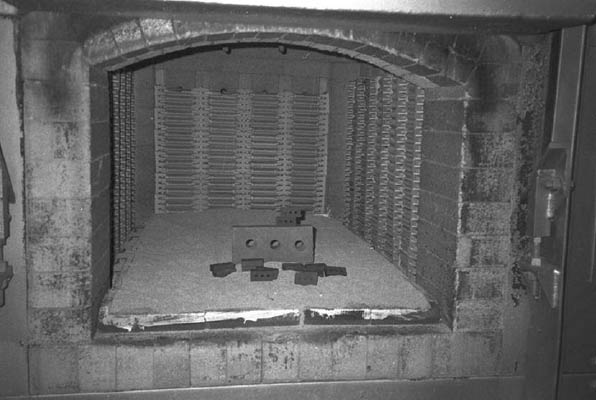
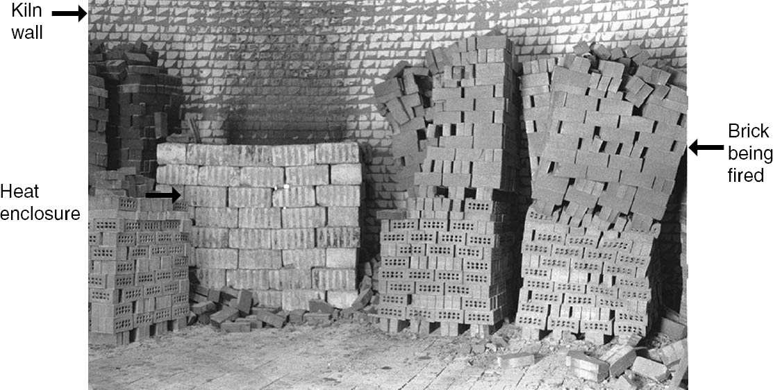
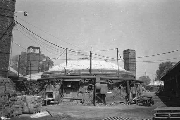
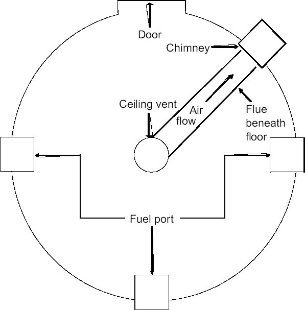
3.2 DOWNDRAFTA more refined version of a draft kiln with better heat distribution was the downdraft kiln, which was especially well suited to burning smaller quantities of higher-grade fuel (Hoehne 1910) and accommodating large quantities of brick (50,000–60,000). The brick were placed in stacks, with narrow spaces between them, to allow the heat to pass around the stacks (BIA 2004); a photograph of the interior of a downdraft kiln can be seen in figure 5. The down-draft kiln incorporated a multitude of evenly spaced fireplaces and a flue beneath the kiln floor. The flames were initially directed upward, and then the heat was drawn downward from the top to fire the brick. The heat was collected by flues, which led to an externally placed chimney. This method promoted a more consistent heat exposure to all brick than the scove kilns, but it still lacked a high level of uniformity in the heat distribution and, thus, in the final product. Similar to the product of scove kilns, a significant portion of downdraft kiln brick were excessively porous and soft (HCF 2002). A popular example of a downdraft kiln dating back to the 17th century was the beehive kiln, which was round and, thus, derived its name from the beehive it resembled (figs. 6, 7). The kiln was made of mortar and previously fired brick, and the dome was wrapped with steel bands to accommodate heat expansion (see fig. 6). The fuel was introduced through side portals at specific points around the circumference of the kiln (see fig. 7). The fire was partitioned from the raw clay units by low wall enclosures (see fig. 5). Even from within one downdraft kiln and across one firing, brick strength and density properties vary, depending on brick position within the kiln. Compressive strength and density tests were conducted in 1907 on brick sampled from various positions (top, one-third height from the top, one-third height from the bottom, and the bottom) within a single kiln firing (table 7). Data from both mud brick and dry-pressed brick from 1907 exhibit a trend of increasing brick strength and density with proximity to the heat source, despite the brick's being formed by two different molding processes. The
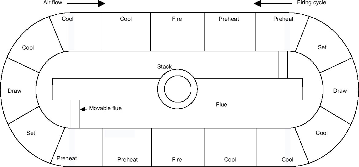
3.3 CONTINUOUS DRAFTInitially used in the first century A.D., chamber kilns are typified by multiple firing sectors within a single kiln. From the beginning, they were extremely fuel efficient because the excess heat from one chamber was transferred to another chamber through the use of flues, thereby minimizing heat wastage. These kilns were widely used until the mid-19th century, at which time the continuous chamber kiln was developed (Rhodes 1981). The continuous chamber kiln invented by Friedrich Hoffman and A. Licht in 1858 was a refinement of the previous design and consisted of a series of single-chamber kilns adjoined to each other. Each chamber is fired sequentially throughout the multipart kiln, and the process of firing, cooling, and brick loading occurs progressively through the series of chambers. Unused heat from one chamber is transferred to the next for preheating (fig. 8). To prevent interruptions in this cycle of preheating, firing, and cooling, the kilns were placed in a circular manner, resulting in a reduction of fuel consumption by two-thirds (Roberts 1962). Stang and associates' 1929 study demonstrated a wide range of brick performance. Based on their manufacturing date, the brick were probably products of a continuous chamber kiln (see table 1), as Hoehne (1910) estimated that by 1910 90–95% of all brick kilns in Europe were continuous chamber kilns and that the trend toward their dominance was beginning in the United States. The original circular chamber design (see fig. 8) was first modified by Hoffman in 1870 to decrease
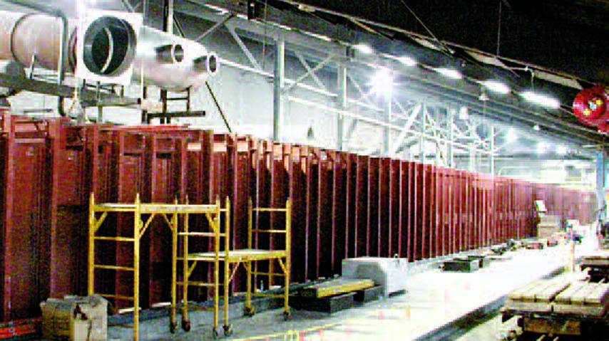
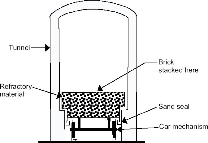
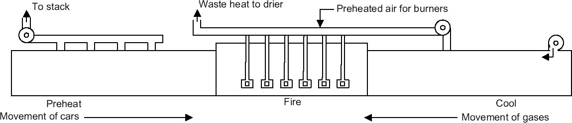
3.4 TUNNEL KILNThe tunnel kiln is similar to the chamber kiln in its continuous application of heat, but differs because it is substantially more heat efficient and because the brick, instead of the heat, move through the kiln. In a tunnel kiln the heat source remains stationary while the brick travel, facilitating mass production and minimizing maintenance costs because the stress on the kiln is reduced (fig. 9). Previous kilns underwent cycles of heating and cooling, which induced cyclical strains in the kiln structure. In contrast, the only portion of the tunnel kiln that is heated remains so continuously (Norton 1957); therefore the heat-based cyclic straining does not occur. Although the first tunnel kiln was built in 1751 in France, these types were not widespread until the late 1800s in England, with O. Bock's innovation in sand seals (fig. 10). Previously, poor seals between the actual cars and the firing chambers failed to insulate the cars' mechanisms from the extreme heat of the fire (Rhodes 1981). The top of Bock's new seal mechanism was made of a refractory material sufficiently thick to protect the metal. Along each side of the kiln walls was a trough filled with sand. A steel blade attached to the cart dipped into the sand trough, creating a highly efficient, gas-tight seal, which is a trademark of modern tunnel kilns (Norton 1957). The earliest tunnel kilns operated in a manner similar to modern kilns in that the brick passed though three stages: preheating, firing, and cooling. The brick were placed on cars that ran on a track through a tunnel adjacent to the heat source. Throughout their preheating cycle, the brick were
As part of the normal 36 hour trip from entering the kiln to exiting it, the brick next passed through the cooling stage. The cooler air entered the end of the tunnel via a blower and was collected at the end of the firing zone. Similar to the draft kilns, the dissi-pating heat from the firing cycle was blown to the beginning of the tunnel for the preheating portion (fig. 11) (Norton 1957). Slow cooling was introduced to reduce cracking and pitting, which could ultimately induce strength loss (BIA 2004). The difference between the modern and early tunnel kiln is the use of blowers for both preheating and cooling. Ducts and blowers promote a more uniform distribution of the heat in the drying, preheating, firing, and cooling cycles (Rhodes 1981). Another reason for improved consistency in later tunnel kilns was the fuel source. Early versions of these tunnel kilns, including Bock's, continued to rely on combustion fuels, such as coal, which had to be continuously fed. When oil and gas burners were introduced (ca. 1900 and ca. 1920, respectively) (Rhodes 1981), the tunnel kilns became more economical and produced a more uniform product because they were less reliant on human tending of the fuel (fig. 12). Since the brick in a tunnel kiln are more uniformly exposed to the same heat treatment throughout the tunnel kiln, there is a much higher level of uniformity in the final product. Furthermore, the actual temperature could then be sustained at a higher temperature (nearly 1093�C versus the typical 538�C found in direct draft kilns) and automatically controlled by computers that continuously monitor and adjust the temperature at various stages of the process and change the speed at which the brick pass through the kiln (BIA 2004).
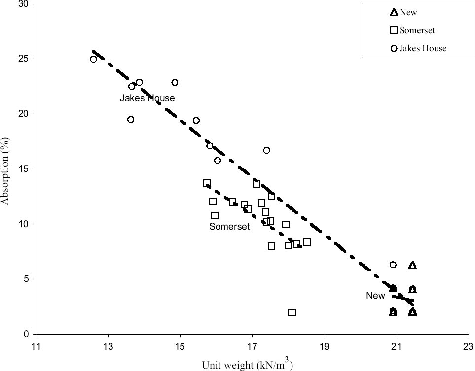
To better understand the impact of kilns on the engineering properties of brick, modern shale units were tested by the authors alongside two highly distinctive sets of pre–Civil War brick. The pre–Civil War brick were salvaged from the demolished Jakes house in Urbana, Illinois, in 2000 (one of the few buildings that predated the Civil War–era railroad through the city) and from the extant main house at Somerset Place, a plantation in eastern North Carolina that most likely dates from 1830 or shortly thereafter. The modern units were fired in a tunnel kiln and obtained randomly from a local supplier in the Raleigh, North Carolina, area from a palette of brick provided for a separate research project. Brick from the pre–Civil War structures were randomly gathered from the project sites. The specific kiln type for the pre–Civil War brick is not known from written records or archaeological remains, but in both cases it is thought to have been fairly primitive because of low compressive strengths and the orange color of the brick, both of which are indicators of low firing temperatures. Nine of each brick type were compression tested as full units: three flat, three on edge, and three on end. The use of all three orientations provide data that would have been more typical of that collected in the 19th century, when the flat testing of a half-brick had not emerged as standard procedure. Absorption testing was done in buckets of cold water for up to 30 minutes or until the brick stopped expelling air to prevent material slaking of brick that were not fully vitrified. Figure 13 plots the unit weight of each brick versus the percentage of absorption as a function of weight over weight. Two distinctive trends emerge:(1) the lighter the unit weight of the brick, the less absorptive it is; and (2) pre–Civil War brick have an extremely broad range of possible unit weights (even within a single project) compared to modern brick. The full results of all the testing are listed in table 8, which emphasizes the relative variability of the pre–Civil War material in all of its engineering properties (e.g., unit weight, compressive strength, and absorption). The unit weight of modern brick was more than twice that of the historic brick and had a coefficient of variation an order of magnitude less than the Jakes house brick and half that for the Somerset Place brick. The consistency of the modern product is most clearly visible in examination of the unit weight (see fig. 13), which is a direct result of the higher firing levels achieved in the tunnel kilns.
The maximum compressive strength of the modern units were on average double that of those from the Jakes house and an order of magnitude greater than those from Somerset Place. The coefficient of variation for the modern brick was half that from Somerset Place and a quarter that from the Jakes house, showing much greater consistency in product in the modern materials. These results were fairly consistent regardless of the orientation of the brick during compression testing. Absorption results were similar in that the modern brick absorbed only a third of the water absorbed by the historic material, but in this case the coefficient of variation for the absorption was nearly as great in the modern material compared to the Jakes house brick and substantially exceeded that of the Somerset Place brick. An alternative method of considering the data is presented in figure 14, where the unit weight is plotted against the compressive strength, but each sample is represented graphically as a function of its absorption level. The size of the circle proportionally shows the brick's relative capacity for absorption. What the figure emphasizes is that although a direct correlation cannot be made between the compressive strength (in any of the testing orientations) and the unit weight or the absorption level, a strong trend is in evidence. What is also interesting to note is that historic brick with unit weights similar to modern material performed at levels equivalent to modern materials, but that these samples were only a fraction of the strength of the modern brick that was tested. Working with material that has experienced 150 years of exposure raises questions as to the impact of age and weather-based deterioration. The topic has been extensively studied elsewhere (see the following references for a sampling of available research: Berra et al. 1993; Bonnell and Pippard 1952; Honeyborne 1990; Hueck-van der Plas 1968; Morton et al. 1990; Sabbioni et al. 1993) and can be considered largely outside the scope of this article since control units were not available to accurately quantify any negative influences of decades of exposure. But a reexamination of figure 14 provides some insight. Unlike a destructive compressive strength test, determination of unit weight can be considered as an inherent brick property. If age or weather removes part of the material, the total weight changes, but the unit weight is unaffected as it represents the existing weight over the existing volume. Unit weight may be considered as an inherent indicator of brick capacity. Such consideration requires additional exploration of historic material, as the limited sample set and restricted access to historic material do not permit more precise correlations or conclusions. |