A HISTORICAL MAP-PRINTING TECHNIQUE: WAX ENGRAVING
NANCY PURINTON
2 TECHNICAL PROCESS
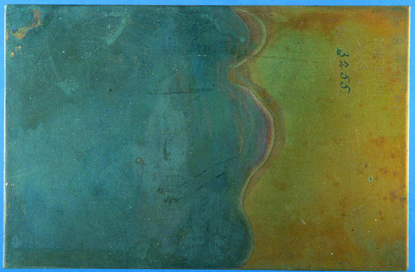
Technically, the first step toward creating the wax-engraved print was to start with a clean, polished copperplate called a case. A diagram of the complete case structure taken from Woodward's book is shown in figure 3 (see page 443). The surface of the copperplate was turned black by applying silver nitrate or a sulfate (of copper or potassium) and thus converting it to copper sulfate (fig. 4, see page 443). The black surface had two purposes. One was to keep the electroplated copper (formed later in the process) from bonding directly to copperplate. The other was to facilitate the drawing process; the combination of black copper sulfate surface and white wax layer (described below) allowed the drawing to be seen easily.
Fig. 3.
Diagram of wax-engraving mold. Used with permission from Wood-ward 1977
 |
Fig. 4.
A partially blackened copperplate. Graphic Arts Collection, National Museum of American History, Smithsonian Institution, photograph 99-1276
 |
Next, a thin coat of white engraving wax was put over the blackened surface. The recipes for this engraving wax were kept secret. Each engraving company had its own recipes, and different formulas were used in summer and in winter. The formulas for wax were crucial to the process because wax that was too hard would chip when cut. The basic ingredients were beeswax, Burgundy pitch from Norway spruce bark, and zinc oxide. The pitch acted as a binding agent. The zinc white obviously whitened the substance but also hardened it. Turpentine was used for thinning the engraving wax, which was ground and poured into molds to form slabs.
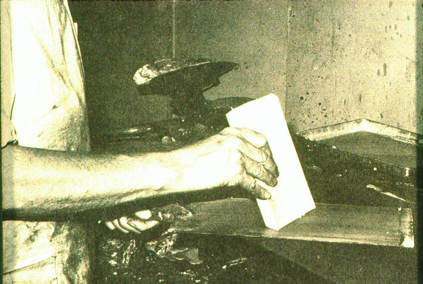
The wax slabs were rubbed on warmed copperplates to coat them. This coating was applied by highly skilled workers because it had to have a very uniform thickness (fig. 5, see page 443). The thickness of the engraving wax layer could vary depending on the use of the plate. “Deep” wax engravings—those with wax up to 1/8 in. (3 mm) thick—were used for coarser work like ruled forms and stationery. Thin wax engravings, with a wax layer as thin as 1/250 in. (.1 mm), combined line work with type. Maps were made using the thin wax-engraving technique.
Fig. 5.
Applying first wax layer to a plate. Used with permission from Woodward 1977
 |
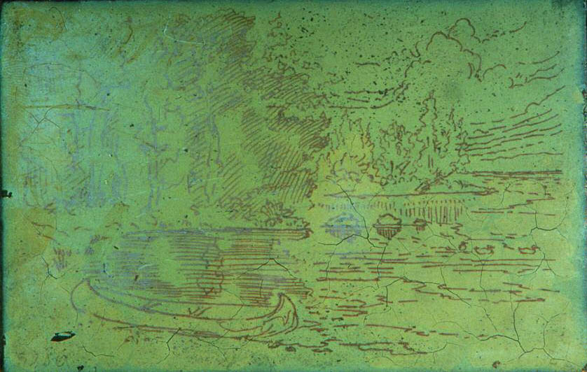
The image could be drawn directly onto the waxed plate or be transferred to the white wax layer by tracing (fig. 6, see page 443). Different materials were used in the tracing/transfer technique, including carbon paper and red chalk. Drawings could be transferred to the wax layer by pressing them while wet onto the wax surface. Later transfer techniques included photography, but photographic images, with their infinite variety of grays, could not be reproduced with this process (Hackleman 1921). If photography was used to transfer a line drawing, the wax surface could be made light sensitive with a solution of albumen, zinc oxide, and silver nitrate. A negative could be placed on the wax and exposed to light to form a positive image. The plate was developed, fixed, rinsed, and dried before going to the engraver.
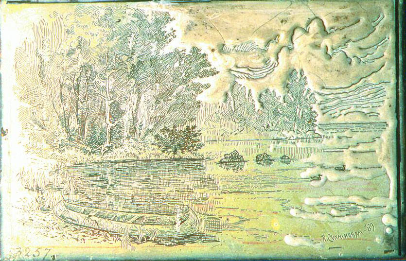
Fig. 6.
Completed drawing on a waxed plate. Graphic Arts Collection, National Museum of American History, Smithsonian Institution, photograph 99-1273
 |
There were two stages in making the map image: engraving and stamping. Both cut the image cleanly into the wax layer without disturbing the black copper sulfate. The engravers were responsible for line work and often made their own tools, called gravers (fig. 7, see page 443). These grooved cutting tools had variously graded points to make a variety of thin, thick, and double parallel lines (Cunningham 1890). The handles of these gravers were thin and delicate—unlike heavier tools used by metal cutters—because very little pressure was required to engrave wax. Tools similar to etching needles could also be used. Wheeled tools with dots and dashes were used to make boundary lines (fig. 8, see page 444). The wax-covered engraving plate was kept warm while the engraver worked.
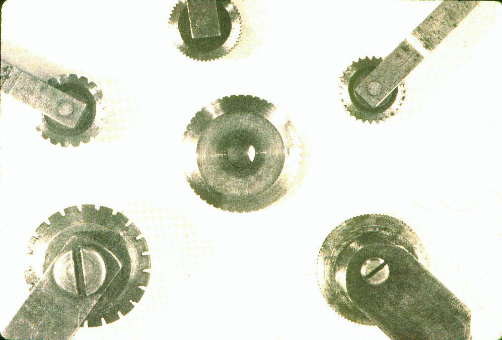
Fig. 7.
A variety of wax-engraving gravers. Author photograph of tools in the Graphic Arts Collection, National Museum of American History, Smithsonian Institution
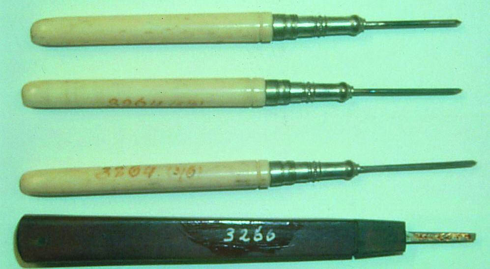 |
Fig. 8.
Wheeled tools for various broken lines. Used with permission from Woodward 1977
 |
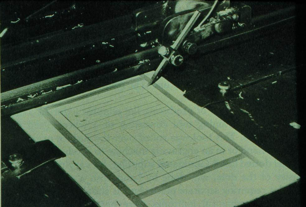
Straight lines could be hand-ruled, but more often they were done on a ruling machine. Figure 9 (see page 444) is an image of the ruling machine at Haas Wax Engraving in Buffalo, New York (Haas 2001). Parallel lines could be made very fine and close (100–150 lines per inch) to create areas of color. Lined areas of different colors could be superimposed to make another color. Straight dashed lines could also be created on this machine to help distinguish different areas on a map.
Fig. 9.
Ruling machine. Used with permission from Woodward 1977
 |
At first, in the maps of Sidney Morse, letters were hand-engraved, but later they were done by stamping with commercially produced dies and type. In fact, the biggest competitive edge for wax engraving was that line and type could be combined in the same relief printing plate. Stamping may not have been faster than hand-lettering, but it was easier. It still required skill but not as much as tiny, precise hand-lettering. The type used in wax-engraved maps was sometimes as small as 3 points (approximately 1 mm).
The type was placed into holders called stamping sticks and then wetted before pressing it carefully and perpendicularly onto the surface and through the wax (fig. 10, see page 444). Stamping machines were a later introduction. Mistakes were corrected by melting the wax smooth to its original thickness and stamping again.
Fig. 10.
The type-stamping process. Used with permission from Woodward 1977
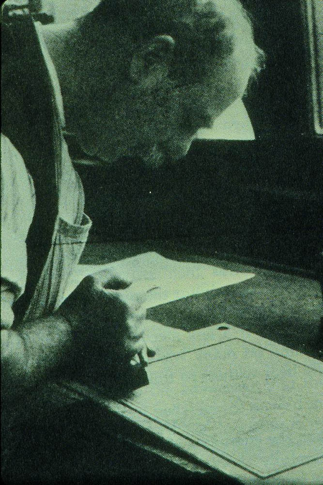 |
The engraving and stamping were done through a wax layer that was often only 1/50 in. (.5 mm) thick. This wax was not deep enough to cast a functional printing plate, so the wax was built up, or additional wax was added, between the engraved lines. This procedure would result in hollows in the actual printing plate (which would be electrotype-cast) deep enough to make inking the plate easy. Building wax was the waste retrieved from old plates and beeswax. It could be tinted to contrast with the engraving wax to make the building-up process easier. It was formed into sticks that were melted with a “building iron” in tiny amounts onto the plate (fig. 11, see page 444). Small spaces less than a few hundredths of an inch wide were not built up. After the wax was built up, a flame was passed over it to smooth it and move it evenly to the edge of the engraved lines. The top right quadrant of the plate in figure 12 (see page 444) is built up.
Fig. 11.
The building-up process. Used with permission from Woodward 1977
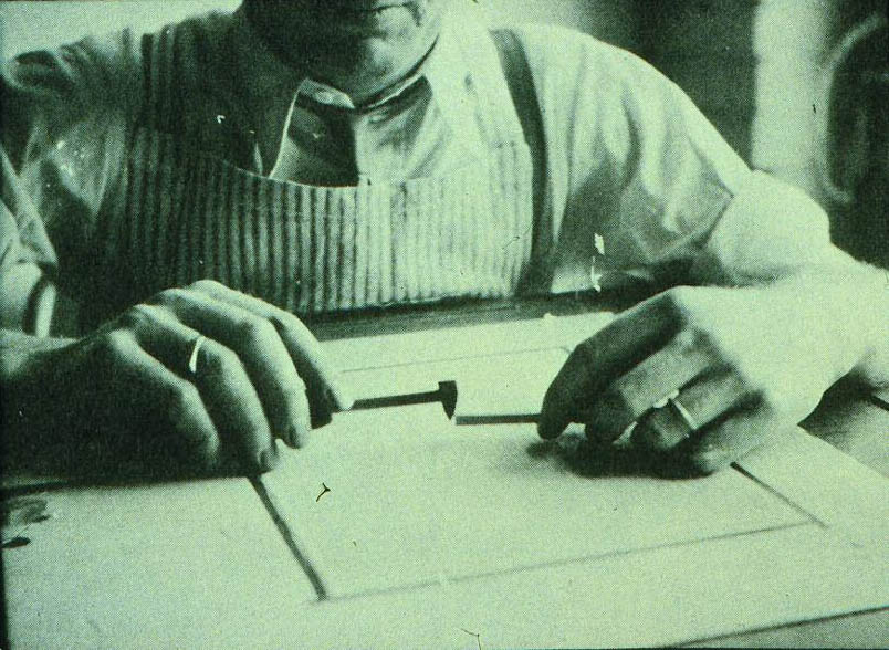 |
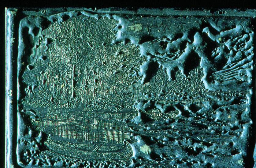
Fig. 12.
Top right quadrant of the plate is built up with wax. Graphic Arts Collection, National Museum of American History, Smithsonian Institution, photograph 99-1274
 |
The prepared wax-engraved plate was covered with a dusting of graphite (fig. 13, see page 444). Then, using a combination of copper sulfate and iron, a thin layer of copper was chemically applied on top of the graphite to prepare the plate for the electrodepositing tank. In the electrodepositing tank the waxed plate was the negative electrode and bars of pure copper were the anodes. The solution in the electrodepositing tank was dilute sulfuric acid. While the waxed plate was immersed in the tank, a copper shell was slowly deposited on the wax image. When complete, the copper shell was separated from the wax using hot water and then backed by soldering type metal (lead alloys) to the copper shell. Although Gascoigne (1986) states that the wax mold was reusable, he appears to be mistaken. Woodward (1977), who describes the mold separation process in detail, says the wax mold is destroyed by the boiling water used to separate the newly cast copperplate from the wax mold. Hackleman (1921) agrees with Woodward that the wax image was destroyed and that the first copper printing plate went unused so duplicate printing plates could be made from it.
Fig. 13.
Graphited plate ready for electrochemical casting. Graphic Arts Collection, National Museum of American History, Smithsonian Institution, photograph 99-1277
 |
The copper printing plate was backed with wood (figs. 14, 15, see page 445). A large wall map could consist of up to 125 copper printing plate sections attached to a wooden base. This was the master plate from which subsequent printing plates were cast or electrotyped. For colored images, each color would have a separate plate. The junctures between the plates were finely done and can be difficult to see. An example is in figure 16 (see page 445).
Fig. 14.
Diagram showing the parts and relationship of the wax-engraving mold and printing plate. Used with permission from Woodward 1977
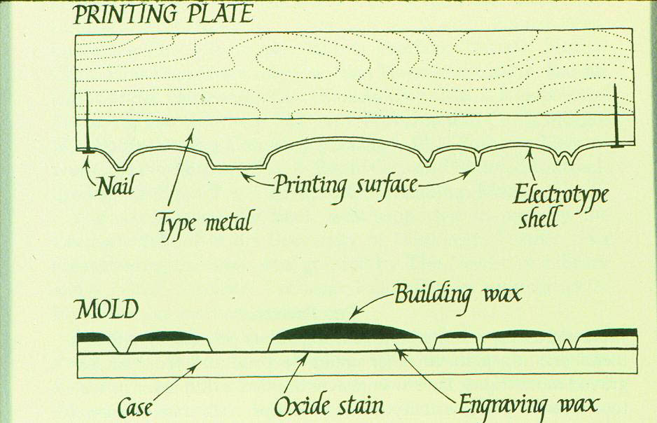 |
Fig. 15.
The cast printing plate backed with wood. Author photograph of plate in Graphic Arts Collection, National Museum of American History, Smithsonian Institution
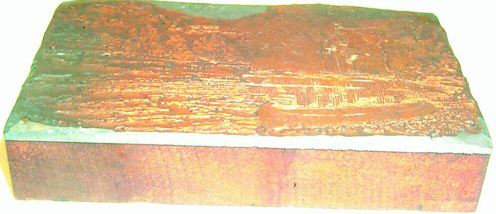 |
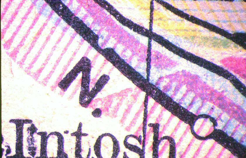
Fig. 16.
Detail (20�) of a map showing the juncture between adjacent copperplates. Author photograph and collection
 |
|