TECHARCHAEOLOGY: WORKS BY JAMES COLEMAN AND VITO ACCONCITIMOTHY VITALE
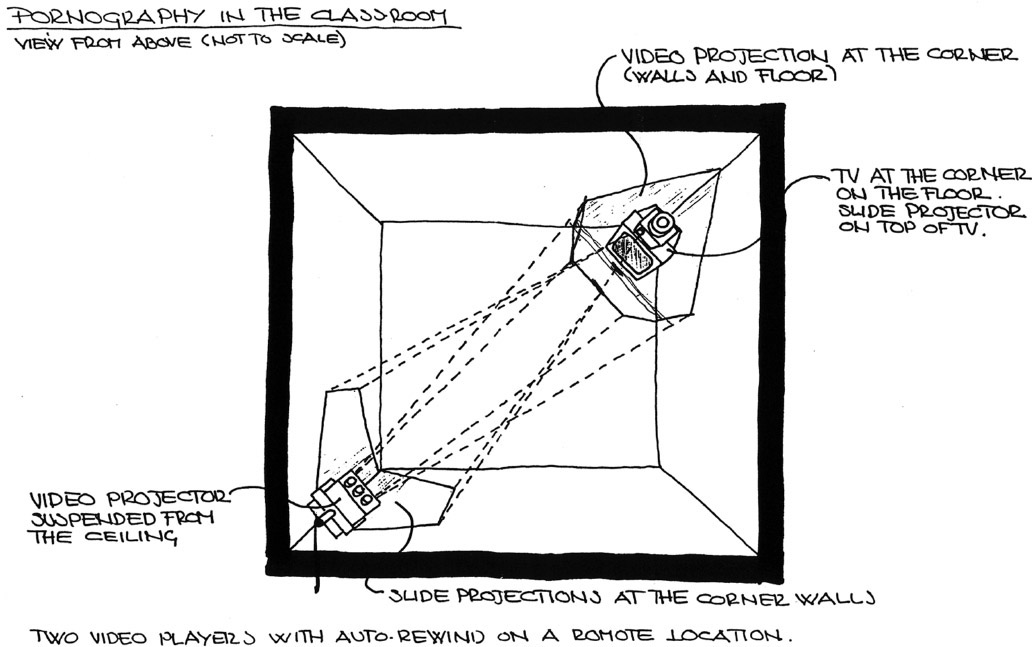
NOTES1. Elements are the discrete visual or audio components in a work, such as slide, video, and Web components. 2. Channels refer to electrical signals in an artwork— video signals, or feeds, or audio signals sent to the speakers. 3. Installation art was not made in multiples prior to the late 1980s (approximately 1987). Artists typically made one-of-a-kind works, and a work was sold only once. The artist could not show the work after it had been sold without the permission of the owner. In the case of Pornography in the Classroom, Acconci, not his gallery, holds the masters; another edition will not be made from them. APPENDIXAPPENDIX A1 WRITTEN DOCUMENTATION FOR VITO ACCONCI'S PORNOGRAPHY IN THE CLASSROOMQuoted from Kramlich Collection (2000) registration materials assembled by the Thea Westreich Art Advisory Services: Monitor image:
Projected images:
Pornography in the Classroom, 1975 (VAT79), includes:
Equipment needed:
APPENDIX B1 CATALOG ENTRY FOR VITO ACCONCI'S PORNOGRAPHY IN THE CLASSROOMSeeing Time catalog entry for Vito Acconci, Pornography in the Classroom(Riley et al. 1999, 144–45).
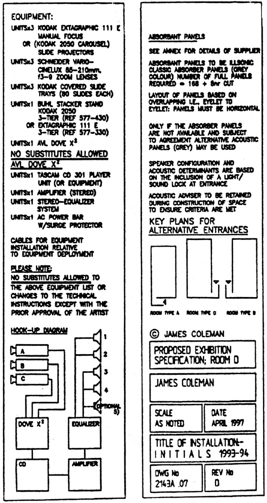
APPENDIX C1 WRITTEN DOCUMENTATION FOR JAMES COLEMAN'S INITIALSQuoted from Kramlich Collection (2000) registration materials assembled by the Thea Westreich Art Advisory Services. The following written documentation was supplied by the James Coleman Studio. A random section was removed at the request of the studio so as not to publish the complete text of the artwork's documentation. 1.1 CURRENT EQUIPMENT LIST (APRIL 1997):
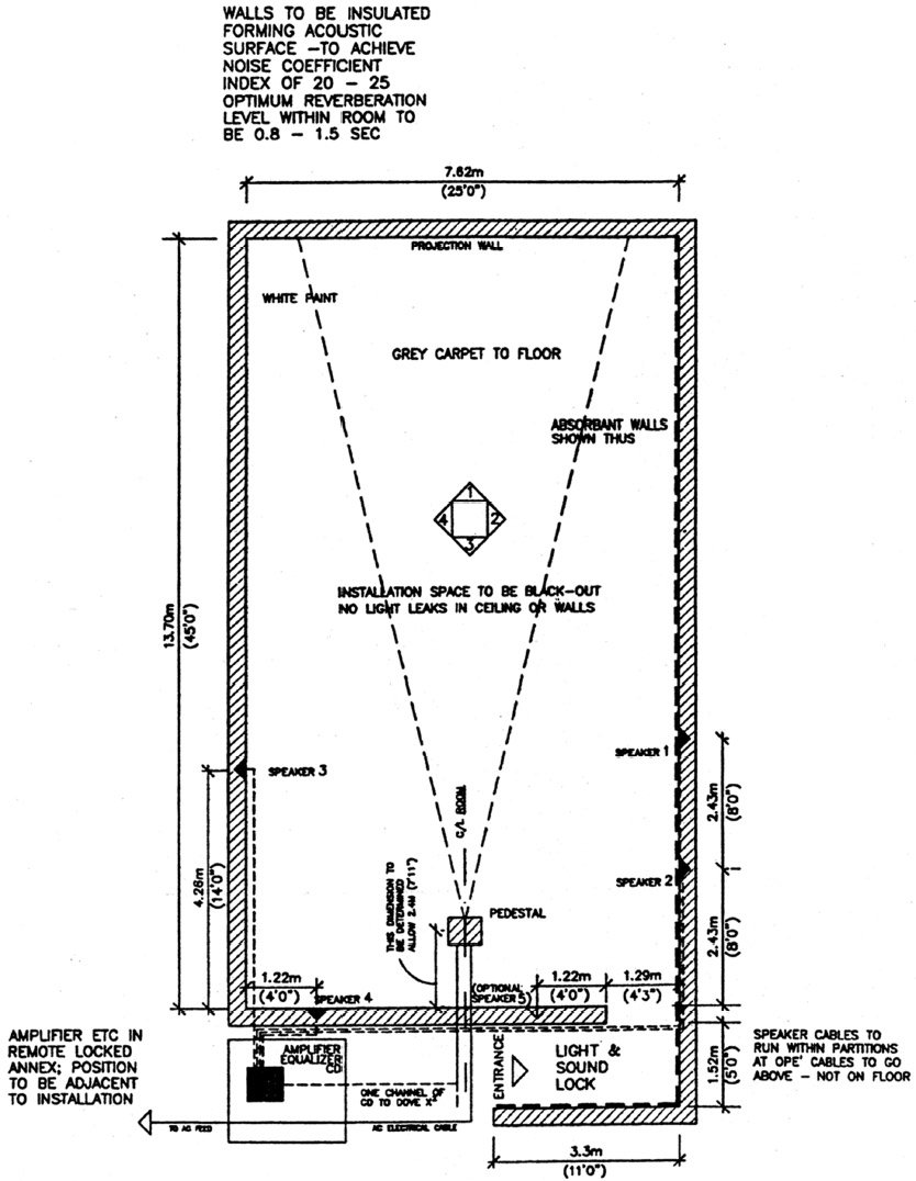
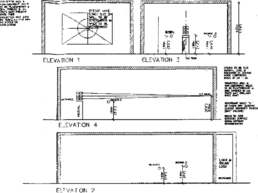
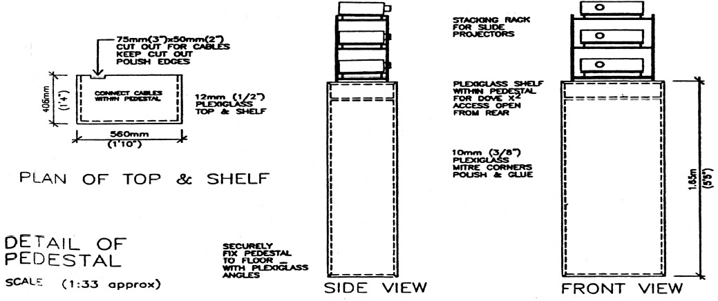
Also required: Cables for equipment installation relative to equipment deployment to include an AC power bar with surge protector Projectors are placed on a Plexiglas pedestal specifically designed for installation and exhibition space (see appendix A architectural drawings). 1.2 TECHNICAL INSTRUCTIONS TO AUDIO-VISUAL (AV) TECHNICIAN FOR “INITIALS” � JAMES Coleman1.2.1 INTRODUCTIONThe work is installed in a space (blackout) specified in the drawings to accompany these notes. Installation of the equipment and the alignment of the projectors is carried out by an experienced, professional AV technician. Due to the fragility of the slides and software, only experienced technicians must install the work. Consult the architectural room plan, which includes detailed technical instructions for installation. Under no circumstances should slide material be brought into the space before the technical installation is completed. 1.2.2 PRIOR TO INSTALLATION1.2.2.1 Equipment CheckCheck that:
1.2.2.2 Room CheckNote: Check that there are no light leaks through cracks or openings in the ceiling or walls. Check that all construction and preparatory work in exhibition space is complete, i.e., (1) cable-laying, (2) loud-speaker installation, (3) acoustic insulation, (4) carpet-laying, (5) painting. Check that space is thoroughly vacuum-cleaned after construction work is completed.
Note: After vacuum cleaning, a minimum time of six hours has to be allowed for dust to settle before the installation of slide projectors and equipment may begin. 1.2.3 PROCEED WITH INSTALLATION IN THE FOLLOWING ORDER[The text from the following sections was omitted at Coleman Studio's request.]
Condensation: The exhibition space should be kept at a constant temperature of not less than approx. 20� Celsius to avoid condensation during projection. Condensation can be very damaging to the images. Dust: Dust levels must be kept to a minimum in the exhibition space. The images must be periodically checked for dust and dirt. When slides have to be cleaned, this work must be undertaken only by a professional slide-lab technician. The laboratory will be equipped with the adequate facilities, i.e., anti-static air and brush-cleaning. All images are mounted in WESS mounts, a number of spare mounts are included. It is important that the technician carefully removes one slide only at a time of cleaning and replaces it in the cleaned WESS mount prior to opening a second image. This is necessary to avoid any risk of slides being replaced in incorrect mounts. After cleaning the slide and slide mount, the technician must be careful not to reverse the slide. All slides are coded and must be replaced in the exact slide with tray number. Any mistake will destroy the sequence of images to audio-synchronization and the integrity of the presentation of the work. After extended projection hours, the color of images will depreciate and eventually fade. At this point the entire set of images (trays A, B, and C) must be replaced. It is not possible to replace only the faded images. New complete copies and duplicates of the work may be acquired through Art Productions. Please allow six months for reproduction when you order. Please quote the confidential ordering number supplied in the acquisition contract. APPENDIX D1 EXCERPTS FROM “WHY DATA VERIFICATION IS NOT ENOUGH!”Copyright � 1995 Gordon Rudd at www.cloversystems.com/verisnot.htm 1.1 Cross Interleave Reed-Solomon Code (Rudd 1995)All CDs incorporate an error detection and correction scheme known as Cross Interleave Reed-Solomon Code (CIRC). It would be impossible to make a usable CD without this error correction, since many errors are generated playing even the best discs under ideal conditions. CIRC is a powerful error detection code that can detect and completely correct all errors on a reasonably good disc. It relies on two principles for its operation. One is redun-dancy. Extra parity bits are added to the data stream to facilitate error detection and correction. These extra bits reduce the available capacity of the CD by about 25%. The other principle is interleaving. The data is not recorded on the disc in its natural order as it would be on tape or magnetic disk. The data are organized into blocks of 24 bytes (called “symbols” in CIRC terminology). These are the blocks referred to in the Block Error Rule measure. Four parity bytes are added to each block of 24 symbols (bytes), making the block 32 bytes long. The data symbols belonging to one block are then distributed over a fairly large area of the disc by “interleaving” them with symbols from other data blocks. The 24 symbols of one data block end up distributed over 109 data blocks. The advantage of this technique is that physical defects on the disc do not eliminate complete data blocks, but instead, parts of many blocks. These partially bad blocks can then be reconstructed using the parity information. CIRC error correction is done in two stages referred to as C1 and C2, with deinterleaving of the data taking place between the stages. The C1 stage is used to recover from random errors caused by noise in the signal; the C2 stage is used to recover from larger errors caused by physical defects such as scratches and dirt. The error correction chip typically can correct two bad symbols per block in the first stage, and two bad symbols per block in the second stage. Some chips can correct four bad symbols in the second stage. 1.2 Layered Error Detection Code and Error Correction CodeCD-ROMs include an extra layer of error detection and correction, usually called Layered Error Detection Code and Error Correction Code (for brevity's sake, typically referred to as Layered ECC), that works similarly to CIRC by adding parity information to each data block. The extra error correction capability can correct errors that are not correctable by the CIRC because it adds additional parity bytes and additional scrambling of the data. APPENDIX E1 DENSITOMETRYThere are two basic methods of measuring film color, densitometry and colorimetry (see below). The traditional method for measuring film is densitometry, a photographic technology developed in the era of black-and-white film and prints. Densitometry is more sensitive to changes in darks than in lights. It is not as sensitive as the human eye (Popson 1989). When densitometry is applied to color, filters are incrementally placed over the light sources, and the three resulting values are run through an equation to yield the single number measurement. Another method is to measure a specific color patch using a gray scale—that is, measuring just the lightness or darkness of the patch, not the color. A single number is reported for a specific color patch, based on the original density. Shift in color tint would not be noted using this method. Density (D) has a logarithmic scale. A density of 2.0 is 10 times as dark as 1.0; a density of 3.0 is 100 times darker than 1.0. Few materials have a density greater than 4.0. Color transparencies generally have a density range of 0.05 to 1.0–1.6. The author's Kodak Q60 (IT8.7/1) 1999:03 transparency color target has a density range of 0.11 to 1.40. The thinnest colors are at about 0.15D. In practice, a density measurement would be made before exposure to light (T1) and then measured again after exposure (T2). If the difference (T1 – T2 = ∂1–2) is less than 0.3 of T1(30% of the original The measurement in a thinly colored area could easily fall below the native repeatability of the density measurement, which is 0.01 (Popson 1989). The precision of any actual instrument is often less than theoretical limits of the measurement, so a measurement could be so small as to fall below the abilities of a specific instrument; that is, a significant change could be present, but it could not be measured by the densitometer. Examples in Coleman's work would be thin colors such as light blue background or a delicate yellow tint in a cream-colored item of clothing. The percentage of density change is calculated from the beginning measurement for the color being evaluated. If the color to be measured has just a slight tint (0.15–0.25D), a 30% change will be a relatively small amount. If the color has a medium density (0.6–1), the change will be much larger, and small changes (10–20%) will be instrumentally perceptible. Densitometry is not ideal for measuring differences in color, although it is the traditional tool for measuring photographic materials. 2 COLORIMETRYColorimetry is a method of measuring color with three-value (tristimulus) color spaces using basic XYZ color coordinates. It is the standard for the measurement of color. Colorimetry data is commonly output in several alternate color spaces, with L*a*b* (Lab star) the most dominant at this time in digital imaging. Delta E (δE) is a method of determining change in two colorimetric measurements. The δE equation for the L*a*b* color space is: δE = [(δL*2) + (δa*2) + (δb*2)]1/2, where δL* = δL*x –δL*y, and where x >and y are taken from the same site at different times. It is generally advisable to make at least three (if not nine) measurements and average them before making the δE calculations. The units of color change in colorimetric measurements, δE, are of equal value across the scale. The best human perception is 1δE for trained observers, and 3–5 δE for the average person. The theoretical limit of detection is 0.05. In practice, good instruments have a precision of about 0.1, thus 0.1δE is the commonly accepted measurement precision. Colorimetry is 13–20 times more sensitive than the human eye (Popson 1989). A change of 20δE is quite large. Coleman's estimate of 30% difference could be calculated as follows: the L* axis has a value of 0–100, while a* and b* have values from –60 to +60, or 120 units, from one pole to another. The maximum δE is therefore 197. A 30% difference of the absolute maximum (197) is 59.1 δE units. This is a very large difference. Clearly, a 30% δE is not an effective analog to the density measurement, because red and yellow are about 30% different in δE in the L*a*b* color space. If colorimetry is going to be used, the degree of “difference” permissible should be several times the perceptual ability of the average human, about 10 δE in critical situations and 20 δE units for normal applications. Colorimetry is more sensitive to color change than the human eye, and it is especially critical for measuring slight changes in small amounts of color (where fading occurs first) (Popson 1989). Hand-held devices for measuring reflective color have become very inexpensive. In mid-2001, however, there are no “inexpensive” methods of making transmission colorimetric measurements. Measurement of film requires an integrated light source; these devices are still expensive. The Gretag-Macbeth SpectroScan T comes in a hand-held version with an integrated light source for transmission measurement of film. Bench-top units are more expensive. ACKNOWLEDGEMENTSThe author extends a special thanks to Christopher Eamon, curator of the Kramlich Collection, for editing this text. Eamon also helped resolve the issues The two excellent artworks in this “TechArchae-ological” analysis reflect the fine efforts of the artists, their galleries, the agents of the Kramlich Collection, SFMOMA's installation, curatorial, and conservation staff, and Mona Jimenez and Paul Messier, who organized the TechArchaeology Symposium in 1999–2000. The author has made a good-faith effort to get accurate technical information, but it is only as good as the era in which it was gathered. Technological eras are becoming shorter, and in the near future (one to four years), these technical projections will need to be reconsidered based on newer technology REFERENCESAcconci, V.2001. Personal communication. Acconci lecturing at CCAC, San Francisco, Calif. Coleman, A. J.2001. Personal communication. Spokesman for James Coleman, Marian Goodman Gallery, 24 W. 57th St., New York, NY 10019. Cooke, L.1995. Introduction to James Coleman: Projected images, 1972–1994.New York: Dia Center for the Arts. www.diacenter.org/exhibs/coleman/coleman.html (accessed October 2000). Dye, S.2000. Personal communication. New media installer, SFMOMA, 151 Third St., San Francisco, Calif. 94103. Kramlich Collection. 2000. Personal communication. Information provided by Thea Westreich/Art Advisory Service, 114 Greene St., New York, NY 10012. Krauss, R.1997. … And then turn away? James Coleman.Vienna: Wiener Secession; Brussels: Yves Gavaert. Laurenson, P.2001. Personal communication. Tate, Millbank, London SW1P4RG. Popson, S. J.1989. A comparison of densitometers and colorimeters. TAPPI Journal2(3):119–21. Real, W.2001. TechArchaeology: Toward guidelines for practice in the preservation and documentation of installation art. Journal of the American Institute for Conservation40:211–31. Riley, R. R., M.Sturken, and C.Iles. 1999. Seeing Time: Selections from the Pamela and Richard Kramlich Collection of Media Art.San Francisco: San Francisco Museum of Modern Art. Rudd, G.1995. Why data verification is not enough! www.cloversystems.com/verisnot.htm (accessed 1995); also available from www.archive.com. Sterrett, J.2000. Personal communication. Director of conservation, SFMOMA, 151 Third St., San Franciso, Calif. 94103. Tuer, D.1996. Blindness and insight: The act of interrogating vision in the work of James Coleman. In Robert Lehman Lectures on Contemporary Art, no. 1, ed. L.Cooke and K.Kelly. New York: Dia Center for the Arts. Wilhelm, H., and C.Brower. 1993. The permanence and care of color photographs: Traditional and digital color prints, color negatives, slides and motion pictures. Grinnell, Iowa: Preservation Publishing. Zippay, L.1991. Electronic arts intermix: Video. New York: Electronic Art Intermix. AUTHOR INFORMATIONTIMOTHY VITALE is a conservator and consultant with more than 30 years' experience in treatment, survey, research, imaging, management, and consulting. Institutional venues where he has worked include Winterthur Museum, Museum of Fine Arts, Boston, Pierpont Morgan Library, National Archives, Smithsonian Institution, and Glasgow School of Art. Now in private practice, Preservation Associates, he works out of his Emeryville, California, imaging studio and the Oakland Museum Conservation Center's paper conservation laboratory in Oakland, California. He has a bachelor's degree in art history and chemistry from California State University at San Jose (1974) and a master of science degree in art conservation from the University of Delaware (1977). Address: 1500 Park Avenue, #132, Emeryville, Calif. 94608. |