LIGHT PIPING: A NEW LIGHTING SYSTEM FOR MUSEUM CASESCATHERINE SEASE
ABSTRACT—Utilizing the new technology of prismatic film, Field Museum has devised a system for illuminating exhibit cases. The light piping system has many advantages over traditional lighting systems. As the lighting fixture is not located inside the case, there is much less heat buildup, and the contents of the case are not disturbed when fixtures or light bulbs need maintenance or changing. The light piping system provides exhibit designers with greater flexibility while safeguarding the preservation of the collections on display. 1 INTRODUCTIONIn November 1988, Field Museum opened its Inside Ancient Egypt exhibit. This exhibit utilizes a new lighting system to illuminate a large case, a reconstructed shrine, and simulated burial niches. This system, referred to at Field Museum as “light piping,” is based on the technology of prismatic film first developed by TIR Systems of Canada and further developed and marketed by 3M Corporation for commercial lighting and sign-age. The potential of the system for museum exhibit lighting was recognized by Paul Martin, then lighting designer at Field Museum, who developed the light piping illuminators described in this paper. The light piping system is a radical departure from the lighting systems previously used in the museum. In other exhibits, the majority of display cases utilize fluorescent lamps in boxes located on the top of each case. Previous temporary installations have used incandescent lighting. These lighting methods have been of concern to conservators for several reasons. First, the light boxes utilize fluorescent lamps that emit ultraviolet light, which is damaging to many of the objects inside the cases. Ultraviolet-absorbing sleeves have only recently been used to limit ultraviolet emissions. Second, accidents have occurred when light bulbs were replaced; for example, falling bulbs or tools have broken objects inside the cases. In addition, starting with the Inside Ancient Egypt exhibit, the climate inside most of the cases is controlled with humidity modules (Sease 1990, 1991). The environmental control of these cases would be disrupted by servicing light fixtures within them, and thereby subjecting their contents to sudden changes in relative humidity. As the light boxes are located on top of cases and are vented, heat buildup within the cases is not an issue at Field Museum. It is, however, an important conservation consideration in museums in which exhibit cases have internal light fixtures. To eliminate the problems of heat buildup inside cases and the disruption of cases when light bulbs or fixtures are changed, the light piping system was chosen as the best means of lighting the somewhat unusual Inside Ancient Egypt cases. Light pipe illuminators provide a flexible, cost-effective means of safely lighting display cases while at the same time providing maximum flexibility and creativity to exhibit designers. The piping system can be used to get light into 2 PRISMATIC FILMThe main component of the light piping system is a prismatic film manufactured by 3M Corporation. Originally marketed as Scotch Lamp Film, it is now called 3M Optical Lighting Film. Utilizing the physical principle of total internal reflection (see below), a pipe of this film transports light, transforming a point source of light evenly into a uniform linear or area source. Optical Lighting Film is made of either transparent acrylic or polycarbonate polymer in sheet form approximately 20 mils thick (Saxe 1989). Lightweight and flexible, it is smooth on one side and grooved on the other (fig. 1). These grooves are actually precise tiny prisms on 14 mil centers (Saxe et al. 1986) that are responsible for the light piping system's high efficiency in propagating light. Acting as total internal reflection mirrors, these prisms prevent light from escaping from the pipe. This efficiency is increased by the fact that little light is absorbed by the transparent, colorless prismatic film. In fact, light actually spends very little time in the thin film wall, traveling predominantly through the nonabsorptive air within the pipe (Saxe et al. 1986).
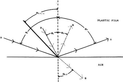
3 THE LIGHT PIPING ILLUMINATORA light piping illuminator consists of a roll of Optical Lighting Film supported by an opaque white plastic tube. The tube acts solely as a rigid support for the film, while its white color helps prevent light from being absorbed. A light piping illuminator is made by cutting a piece of Optical Lighting Film to fit the circumference and length of the tube. It is then rolled and inserted into the tube, with the smooth side of the film facing inward and the prism grooves running parallel to the axis of the tube. A light source is placed at one end of the illuminator, positioned to direct a beam of light into it. Although the film is flexible, it will crack along the prisms if rolled too tightly. For this reason, the manufacturers do not recommend making illuminators less than 3 in diameter (3M 1988). It is not necessary to affix the roll of film to the tube in any way. Utilizing different properties of the Optical Lighting Film, a light pipe illuminator can do two things with light. First, it can simply transport the light down the length of the pipe. Second, Optical Lighting Film can also be used to extract light from the pipe anywhere along its length. Before discussing these uses in detail, it is first necessary to 4 PRINCIPLE OF OPERATION4.1 TOTAL INTERNAL REFLECTION (TIR)Total internal reflection is the complete reflection of a ray of light within a medium from a surrounding surface back into that medium (Total internal reflection 1986). This phenomenon permits the efficient transportation of light in fiber optic cables and in light pipe illuminators. As illustrated in figure 2, when a light ray is incident on a boundary between two transparent media that have different refractive indices, a certain amount of light is reflected, with the angle of incidence equaling the angle of reflection. The remainder of the light is transmitted through the boundary with refraction of the ray. The angle of refraction is given by the well-known relationship, Snell's Law. TIR of a light ray incident on a boundary occurs only when the ray approaches the boundary in the medium of higher refractive index and its angle of incidence has a value greater than a certain critical value, called the critical angle. The value of the critical angle is determined by the refractive indices of the two media in contact at the boundary. In the case of the light pipe illuminator, one medium is air and the other is the plastic of the acrylic or polycarbonate Optical Lighting Film for which the critical angles are 42� and 39� respectively.
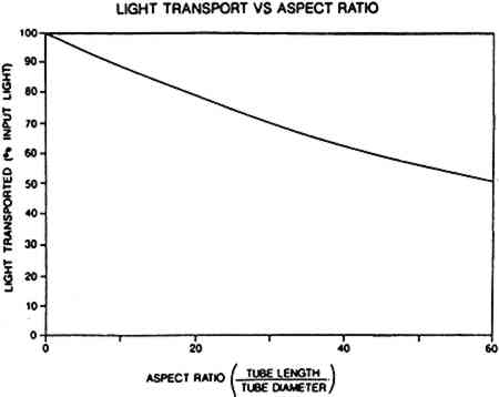
4.2 LIGHT FALL-OFFAlthough the efficiency of the prismatic film is high, there will be some light loss, approximately 30%, as the beam travels down the pipe. This loss is caused by slight microscopic imperfections in the prisms (Saxe et al. 1986). Figure 3 shows how light diminishes as it travels down a pipe and enables one to predict approximately the performance of a light piping illuminator. The aspect ratio on the horizontal axis is the ratio of the pipe length to its diameter:
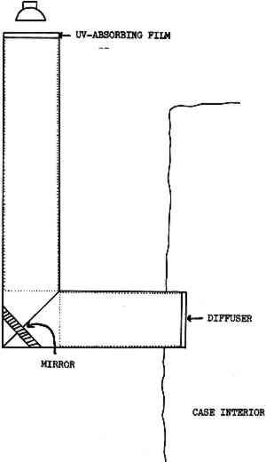
It is important to note that this is a ratio. Thus, the aspect ratio of a pipe 4 in diameter and 120 in (10 ft) long will be the same as that of a pipe 8 in in diameter and 240 in (20 ft) long. For both, the ratio is 30. This means that the light transport properties of both pipes will be the same. Thus, using the chart in figure 3, it can be determined that for these two pipes approximately 70% of It should be pointed out that this chart is only approximate. The actual efficiency of any given light piping illuminator will depend on the type of light source, extractor film, and reflector used and any alterations made to the pipe (3M 1988), which will be discussed below. To effectively transport and uniformly distribute light, the manufacturers calculate that the maximum aspect ratio is 40 to 1. Uniform distribution will be lessened at ratios higher than 40, but sometimes this effect can be counteracted by using a light source at both ends of the pipe. For pipes with aspect ratios less than 30, it is necessary to use an extractor film to distribute light evenly (3M 1988). 4.3 BENDING LIGHTAnother important feature of the light piping system is that it can direct light around corners as well as in a straight line. Bending can be achieved by positioning a mirror at the juncture of two pipes joined at an angle as shown in figure 4. Light enters one pipe and is transported by TIR down to the end, where it hits the mirror. The mirror redirects it into the second pipe, where it is transported down this pipe and comes out the end to illuminate the case.
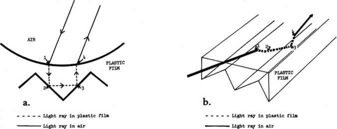
4.4 TRANSMISSION OF ULTRAVIOLET LIGHTWhile no quantitative experiments have been reported on the transportation of ultraviolet light down a pipe, there are good reasons to believe that ultraviolet light will be selectively absorbed by piping. Both acrylic and polycarbonate absorb ultraviolet light, and the cumulative effect of light bouncing many times against the film as it moves down the tube should almost totally eliminate any wavelengths below approximately 380 nm (Saxe 1992). It stands Tests were undertaken at Field Museum to measure whether ultraviolet light is transported down a piping illuminator. A Crawford meter was used, which measures the ultraviolet content (UVC) of light in microwatts (μw) of ultraviolet light per lumen of visible light. The measurements showed that preferential absorption of the ultraviolet wavelengths occurred in the light pipe illuminator. The light source emitted light with a UVC of 150 μw/lumen. At the end of a 1 ft long illuminator, the UVC of the light was well below 50 μw/lumen. As the meter is not calibrated below 50 μw/ lumen, longer illuminators were not tested. Even though ultraviolet light levels with the illuminators are kept below the generally recommended level of 75 μw/lumen, all illuminators used at Field Museum are used in conjunction with ultraviolet-absorbing filters adhered to the light source end of the tube. Such a filter will also protect the degradation of the prismatic film itself over long exposure and is recommended when high ultraviolet-emitting light sources are used (Saxe 1992). 5 APPLICATION OF THE LIGHT PIPING ILLUMINATORSIt can be seen that the prismatic film has very efficient reflective and transmissive properties, depending on the angle at which light strikes the film. Both properties are utilized in the light piping illuminators to produce either a spot of light or an area source of light in the following manner. 5.1 POINT SOURCE OR SPOTLIGHTWhen used to make a spotlight, only the reflective property of the Optical Lighting Film is used. Light is simply transported down the length of the pipe by multiple TIR, that is, repeated total internal reflection. Light enters the pipe and strikes the smooth surface of the film. Some light is simply reflected there and continues to move down the pipe through the air. The remainder passes through the surface of the film with refraction and travels on to strike one of the prism surfaces (fig. 5a, b). As
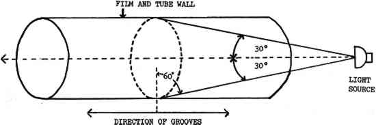
So that the light can pass through the pipe with a minimum number of surface reflections from the prismatic film and, hence, minimum attenuation, the rays from the source entering the end of the illuminator must strike the surface of the prismatic film at an angle of incidence of 60� or greater. Consequently, when rays are directed into the open end of the pipe from a point source on the pipe axis, those entering rays making an angle of 30� or less with that axis will be most efficiently transported through the illuminator. As is shown in figure 6, these rays will fall within a cone with the point source at its apex and a half-angle of 30�. For this reason, when creating a spotlight, it is important for the light source to utilize reflectors that will contain the beam of light to a cone with a half-angle of 30�.
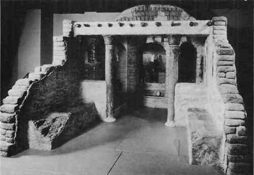
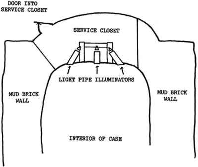
To use the light piping illuminator as a spotlight, the outer pipe is made of opaque white tubing to reduce light loss in the system through leakage. No extractor film is necessary. A disk of frosted Plexiglas can be attached to the far end of the pipe to soften the light beam as it leaves the pipe. Diffusers or lenses can also be placed at the end of the pipe to further control the quality of the light. As mentioned above, the light source should have as narrow a beam as possible so This application of light piping is used in a large case simulating a shrine to the Egyptian cat goddess Bastet (fig. 7). All spotlighting of objects in this case is achieved with light coming through the ends of pipes. The pipe illuminators in this case are made from 3 in diameter polyvinylchloride (PVC) tubing built into the ceiling of the case (fig. 8). Each tube extends downward through the ceiling into the case approximately 2 in. This end is closed off with a frosted diffuser adhered to the end of the tube and is blended into the ceiling of the case with the simulated mud mixture used throughout the interior of the case. The other end extends into the service closet on top of the shrine housing all the light fixtures. This end of the tube is covered with a disc of ultraviolet- absorbing Plexiglas adhered with a PVC glue. The light source for each pipe is a 50 or 75 watt narrow spot quartz lamp.
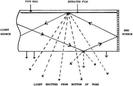
5.2 AREA SOURCES OF LIGHTOptical Lighting Film can also be used to extract light from the pipe anywhere along its length to create an area of light. This area of light is achieved by decreasing the angle of incidence of the light in the pipe with the prismatic film so that it is less than 30�. The ray is then transmitted efficiently through the film rather than being totally reflected by it. These rays are the ones that fall outside the cone in figure 6. This decrease in the angle of incidence enables light to be leaked, or extracted, from the pipe for illumination. Thus, by decreasing their angle of incidence to the prismatic film, it is possible to redirect rays being guided down the pipe. If this angle becomes less than 30�, rays will pass through the film and an opening in the plastic pipe. This angle change can be efficiently achieved with Scotchcal Series 7725 ElectroCut Film, a matte, white, highly reflective film. The Scotchcal film is made of a stable vinyl with a pressure-sensitive adhesive backing (3M 1988). When making the light piping illuminator, the extractor film is adhered to the smooth surface of the prismatic film before it is inserted into the pipe. By increasing the angle at which the ray hits the prismatic film, this film acts as an “extractor,” redirecting light rays and causing them to scatter at different angles, as shown in figure 9, roughly doubling the amount of transmitted, or leaked light (Saxe 1989). The addition of a mirror at the end of the pipe will serve to force light back down the pipe, increasing the light transmission
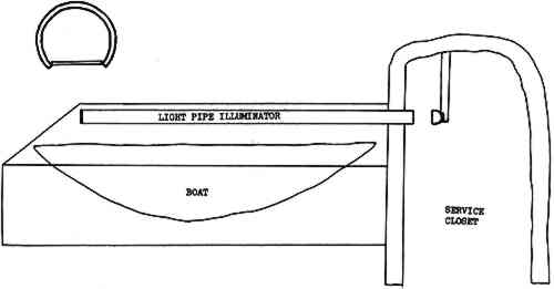
The shape of the extractor film will vary depending on the length of the pipe. For short pipes, the extractor film may not be needed or, if needed, may be only a thin strip. For longer pipes, the extractor film may equal the diameter of the pipe at the far end from the light source and taper down to a thin point near the light source. When opened out flat, the extractor film forms an isosceles triangle. This triangular shape is necessary for the optimum uniformity of light output (3M 1988). Light will diminish as it is transported down the length of the pipe. Therefore, at the far end, where there is relatively little light, a wide piece of extractor film is needed to transmit as much light as possible. At the light source end where there is plenty of light, little or no extractor is needed. To turn a pipe illuminator into a linear or area source of light, the pipe itself must first be modified. If the entire pipe is to be the light source, a tube of clear plastic is used. If only a portion of the pipe is to provide the light, an opaque tube is used with a clear window inserted in the desired place. A piece of Scotchcal Series 7725 ElectroCut Film is adhered to the smooth surface of the Optical Lighting Film before it is inserted into the pipe. A mirror, or mirror film, is affixed to the end of the pipe to reflect light back up the pipe to maintain maximum use of the light. In this application of light piping, both the reflective and the transmissive properties of the film are used. Light is transported down the pipe by reflection as described above. At the same time, the transmissive properties of the prismatic film, aided by the extractor film, allow light to be pushed out of the pipe along its length or through windows cut into the pipe. At Field Museum, the area source application of the piping system is used to illuminate a wooden boat from Pharaonic Egypt. This case is lit by a single pipe suspended below the ridge beam of the case (fig. 10). A single light source is located in a service closet in the simulated mud-brick arch to the right of the case. The light source is a 500 watt quartz bulb.
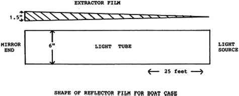
The pipe, made of opaque white PVC tubing, is 6 in in diameter and 300 in (25 ft) long. It is three-quarter round with a flat diffuser acting as a window adhered along the bottom surface. The prismatic film goes all around the inside of the pipe and has extractor film adhered to its smooth surface. This extractor film, shown schematically in figure 11 by hatching, is one-half the radius of the pipe at the mirrored end where there is little light, tapering to a point at the light source end.
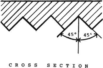
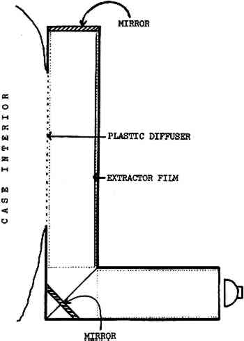
The light pipe for the boat case uses 45 sq ft of prismatic film at a cost of $135 (in 1988), less than the cost of the pipe itself. At the time of writing (1992), the cost of the film is $4–5 per sq ft depending on the quantity purchased. The same technique, but on a smaller scale, is used in conjunction with the light- bending feature to illuminate simulated burial niches. In these cases, almost the entire length of one pipe is actually built into the ceiling of the case. The window in the pipe consists of a frosted plastic diffuser that also serves as a window into the ceiling of the case through which the light enters the case (fig. 12). At the far end of this tube, a second pipe extends perpendicular to the first, forming a mitered corner. Where the two pipes join, a PVC mirror is positioned across the corner with PVC glue to form a 45� angle with the sides of each pipe. The light source is at the end of the second pipe. The light fixtures are located in a service closet behind the niches.
6 CONCLUSIONSThe advantages of the light piping system are many. First, since the light source is not located inside the case there is no heat build- up that could damage the objects inside. Lack of heat buildup is particularly important for objects made of organic materials and hygroscopic materials that are sensitive to heat and drying out as well as of materials that expand and contract when exposed to fluctuations of heat. The remote light source also means that maintenance of fixtures does not entail opening or disturbing the case itself. Thus delicate materials inside the cases are not subjected to any unnecessary handling or potential accidents by maintenance staff. The remote light source also assures that the environment in climate-controlled cases is not disturbed by routine light maintenance. As the focus of each lamp is fixed at the end of the pipes, there is no need to refocus them when bulbs are changed. Thus the integrity of the aesthetic judgments initially made by the lighting designer is preserved. While the technology utilized in this system is “high tech,” its service requirements are “low tech,” requiring no maintenance or moving parts. At most, it may be necessary to replace the prismatic film after roughly 10 years, the estimated life of the film. This life may be extended considerably by using light sources with little or no ultraviolet component or by filtering out the ultraviolet component before the light enters the pipe. Finally, the system allows for maximum flexibility and creativity in exhibit case design, layout, and lighting. Field Museum designers have found this piping system to be extremely flexible in creating a wide variety of lighting effects in cases that would otherwise have been extremely difficult to illuminate. By eliminating some of the problems conservators have with conventional lighting systems, light piping illuminators provide conservators as well as designers with a valuable new tool for exhibition conservation. The applications mentioned here are but a start; prismatic film and the light piping system have tremendous potential for exhibition lighting. ACKNOWLEDGEMENTSI am indebted to Paul Martin, former lighting designer at Field Museum, for providing information about prismatic film in general and our use of it in particular. I am also extremely grateful to Steven G. Saxe, research supervisor at 3M Visual Systems Division, Austin, Texas, for providing information and reading and commenting on various drafts of this paper. REFERENCESSaxe, S. G.1989. Prismatic film light guides: Performance and recent developments. Solar Energy Materials19:95–109. Saxe, S. G.1992. Personal communication. 3M Visual Systems Division, Austin, Tex. Saxe, S. G., L. A.Whitehead, and S.Cobb.1986. Progress in the development of prism light guides. Proceedings of the SPIE (International Society for Optical Engineering) 692:235–40. Sease, C.1990. A new means of controlling relative humidity in exhibit cases. Collection Forum6(1): 12–20. Sease, C.1991. The development of the humidity control module at Field Museum. Journal of the American Institute for Conservation30:187–96. 3M 1988. 3M Scotch™ Optical Lighting Film general theory. St. Paul: 3M Traffic Control Materials Division. 3M 1989. 3M Scotch™ Optical Lighting Film specification sheet. St. Paul: 3M Special Enterprises Program. Total internal reflection. 1986. The New Encyclopaedia Britannica: Micropaedia, 15th ed.11:863. SOURCES OF MATERIALSCrawford UV Monitor type 760Qualimetrics, Inc., P.O. Box 41039, Sacramento, Calif. 95841 #2300 3M Optical Lighting Film, Scotchcal™Series 7725 ElectroCut™ Film, 3M Traffic Control Materials Division, Building 260–5N–14, 3M Center, St. Paul, Minn. 55144 All lamp fixture and bulbs available from lighting suppliers.Shrine case: Lighting Service, Inc., fixture 818D, narrow spot lamps Q50MR16EXT 12 volt, 50 watt, narrow spot lamps Q75MR16EYF 12 volt, 75 watt Boat case:lamp Q500Par56NSF 120 volt, 500 watt Burial niche cases:Swivelier fixture L21828, Sylvania capsule, lights 75Par16/Cap/NSP 120 volt, 75 watt AUTHOR INFORMATIONCATHERINE SEASE is head of the Division of Conservation at Field Museum of Natural History, Chicago. She has an A.B. from Bryn Mawr College and a B.Sc. in conservation from the Institute of Archaeology, University College, London. She taught in the Conservation Department at the Institute of Archaeology prior to joining the staff of the Objects Conservation Department at the Metropolitan Museum of Art in 1979, where she was the head conservator for the installation of the Rockefeller Wing of Primitive Art. She worked privately in New York before joining the staff of the Anthropology Department at Field Museum in 1986. She has worked on numerous excavations in Britain, Greece, and the Middle East. Address: Field Museum of Natural History, Roosevelt Rd. at Lake Shore Dr., Chicago, Ill. 60605.
 Section Index Section Index |