THE DEVELOPMENT OF THE HUMIDITY CONTROL MODULE AT FIELD MUSEUMCATHERINE SEASE
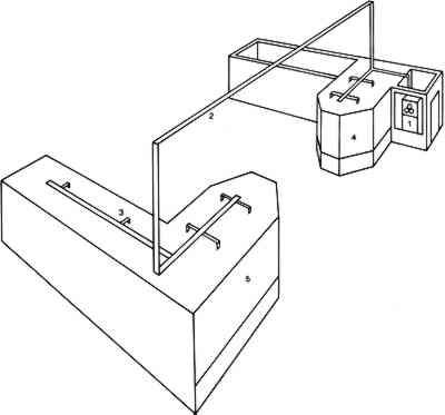
3 THE FIELD MUSEUM MODULEIN 1987, a local Chicago company, Kennedy-Trimnell, built the first module for Field Museum from blueprints provided by the Canadian Conservation Institute. Kennedy-Trimnell now produces the modules commercially. In July 1987, the first module was installed in the Webber Resource Center, a study hall containing Native American ethnographic material. Nearly all of the artifacts on display are composed of moisture-sensitive materials, The module was connected to two large walk-in cases with a combined volume of approximately 3,000 cu ft. A system of plastic tubing was used to connect the module to the cases. Two-inch diameter polyethylene tubing formed the main supply feed from the module to the tops of the cases. The cases face each other, one on the north side of the hall and the other on the south, so it was necessary to suspend a 30-ft length of this tubing from the ceiling to connect the two cases (fig. 3). A 2-in diameter supply tube was installed along the length of the top of each case, with 1/2-in diameter tubes branching off perpendicularly. These smaller tubes were connected to 1/2-in diameter holes perforating the ceiling of each case for the entry of the conditioned air. Once the module was installed, these holes were fitted with plastic plugs with openings of 1/8–1/2 in diameter to regulate the airflow through the cases. A thermal anemometer was used to measure the airflow from each hole. Where the airflow needed to be decreased, a plug with a small hole was used. Where the airflow needed to be increased, a plug with a larger hole was used. In this way, the airflow throughout the system was equalized.
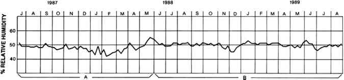
The module was set to maintain the humidity level in the cases at 50%. Recording hygrothermographs were placed in each case as well as in the hall itself to record the ambient relative humidity. The results for the north case, from June 1987 through June 1988, can be seen in figure 4.
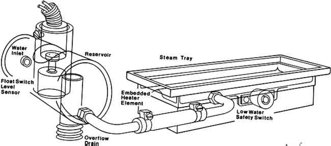
It took the better part of a week for the silica gel column in the module to adjust to its new environment and then to bring the relative humidity in the two cases to the desired level of 50%. Last-minute adjustments to the installation requiring staff access to the cases also affected the fluctuation of relative humidity during this first week. In subsequent weeks in July, August, and September, however, the machine did well. Through the end of August the relative humidity was maintained to within 2% of the set 50%, within 2.5% until the beginning of October. The module did not do as well in the subsequent winter months of 1987–88. During this period the ambient relative humidity in the hall averaged 32%, with a low of 23%. Nineteen weeks out of the 27 weeks, it dipped below 30%. The module was now in a humidification cycle that was not as effective as the dehumidification mode at maintaining 50% RH in the two cases. Although we were concerned about the relative humidity levels in these cases, the use of the module was regarded as a field test. Up to this point, adjustments and minor changes were being made to the module in response to the conditions in the exhibit hall and the behavior of the module. A recurring problem, for example, involved the water supply. Particulate matter in the water sporadically blocked the water line to the module, causing the reservoir and the humidifier's evaporative plates to dry up. During the summer months, when the module was dehumidifying and, therefore, not requiring water, this condition was not a problem. In the winter, however, the module, in its humidification phase, was constantly calling for water, and blockages in the water line prevented the module from maintaining a constant humidity level. To resolve this problem, various particulate filters were connected to the water line over a period of months. Although they improved the situation, they did not solve the problem altogether. The final solution was to increase the size of the tubing on the water line to 1/4 in diameter. Another problem involved the float valve that regulated the filling of the reservoir for the humidifier's evaporative plates. The valve was a mechanical switch attached to a long arm with a float on the end. This assembly was located inside a box that filled with water. As the water level rose, the float moved the end of the arm up shutting the mechanical valve that, in turn, shut off the water flow. The bottom of the box housing the float valve was open on one side to allow water to enter an adjacent box freely. This box contained eight evaporative plates that wicked up the water. When in a humidification cycle, the machine diverted the airflow through the box containing the evaporative plates to pick up moisture. The design of this whole assembly was mechanically cumbersome. The box in which the valve was located was too small and did not allow for a long enough level angle for the valve to work efficiently. As a result, the float valve was not sensitive enough to properly regulate the water supply, and constant readjustments were necessary to keep it working properly. In addition, the water pressure proved too strong for the valve, and it would not shut off the water supply. A pressure reducer was necessary to make the float valve work, but this device created additional problems. Once it exploded, causing a minor flood in the hall. In addition, the entire assembly leaked throughout this whole period. During the winter months, the solenoid, the switch that allowed the reservoir to maintain As the winter progressed, it became clear that the design of the module's humidification system did not enable it to provide enough humidity to maintain a level of 50% RH. To solve this problem, design modifications were made to increase the module's efficiency. As mentioned above, the float valve and evaporative plate system had proved awkward. Equally cumbersome was the way in which the airflow was switched to bypass the evaporative plates when the module was operating in a dehumidification mode. The arrangement made the module more complicated than need be, presenting more opportunities for mechanical failure. The module was simplified by replacing the evaporative plates with a steam generator, located in the cold box, as a means of humidifying the air. As well as providing more humidity, the steam generator system allowed the centrifugal blower to operate closer to its full potential, increasing the possible treated case volume from 3500 to 5500 cu ft. With the steam generator in the same box as the condensate coils, it was no longer necessary to switch the airflow back and forth. The steam generator consists of an electric resistance element embedded in a shallow die-cast tray located in the air intake (fig. 5). The tray is filled with water that is gravity fed from the auxiliary reservoir. The water level in the auxiliary reservoir is controlled by an electric valve consisting of a float valve and a solenoid. Water boiled in the tray provides the humidity needed for the system. The steam generator currently being used has a life of approximately 18 months and a replacement cost of $35 at the time of writing.
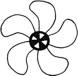
After the steam generator was installed in the last week of May 1988, fluctuations in the RH in the cases decreased to 4% (fig. 4). With the exception of a few periods, fluctuations have remained at this level. The drops in relative humidity, recorded in November and December 1988 and March 1989, occurred when safety switches in the module turned it off, when the fan motor and the solenoid burned out and when the steam generator tray needed cleaning. These problems led to further modifications of the module, the most significant of which was making the fan self-cooling. The fan blade assembly
There was one instance of overhumidification, when the module failed to stop humidifying the air when it reached the 50% level. The plastic tubing connecting the humidistat with the center of the silica gel column had become kinked, and the relative humidity in the cases gradually reached 62% over a three-week period. At the time, the module was being monitored at monthly intervals. When the problem was discovered, the tubing was replaced with a thicker walled tubing while maintaining the original 1/8-in opening. The problem has not recurred. Maintenance of the modified module has been minimal. Once the steam generator was in use, the only chronic problem was with the water source, which will be discussed below. |