RESTORATION OF A LARGE CHINESE BRONZE URNAron A. Apisdorf
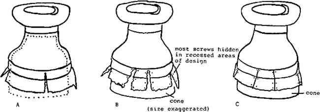
4 TREATMENT OF LEVEL I (THE LOWEST PART OF THE URN)The first problem tackled was that of improving the ability of Level I to bear the weight of the upper levels. I considered using a brass strip welded into a ring and inserted into the base to take over weight-bearing from the damaged bronze base. I feared, however, that the weld might eventually succumb to the pressures on it and open and press outward on the base. I decided instead to use a cone-shaped fiberglass ring eighteen inches tall and nearly the same diameter and shape as the urn (wide at the bottom, narrower at the top). The fiberglass ring was from a commercially made object (a flower pot), which I cut to a ring three-quarters of an inch thick at its base and two-thirds inch thick at the top. This reinforcing ring was fitted into the urn so that it extended one inch below the original bronze base in order to have the fiberglass function as the actual weight-bearing support (Fig. 3A). (This was aesthetically acceptable to the owner as he planned to stand the urn on a carpeted area and expected that the pile of the carpet would for the most part conceal the fiberglass at the base.)
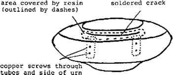
Round-headed brass screws (4–32) three and one-half inches long and brass nuts were used to attach the fiberglass to the bronze. Brass was used because it is compatible with bronze and would not cause an electrolytic reaction. Four screws were attached with the head on the outside of the urn, about four and one-half inches from the floor in the strongest parts of the base. Then screws were attached in pairs three-quarters of an inch from each side of the fissures, two to three pairs per fissure (Fig. 3B). These pairs of screws were tightened to the fiberglass slowly, using equal pressure, beginning at the narrowest point of the fissure and progressing toward the widest part of the opening. Because the circumference of the fiberglass was just slightly less than the original circumference of the base, screwing the bronze to the fiberglass in this way resulted in the closing of the fissures completely without additional metal fatigue (Fig. 3C). Next, the depressed area on the uppermost part of Level I was forced back into position to match the other side, by applying pressure from inside the urn. In order to hold together the two sides of the twelve-inch crack, I considered brazing, soldering with 50/50 solder or soldering with 60/40 solder. I rejected brazing because it is a method that requires heat so high that I feared it would fatigue the metal, since the surrounding area was still porous. I chose to use 60/40 solder (and Burnley soldering paste as flux) because it flows more easily than 50/50 and as a result it flowed into the adjoining porous area and reinforced it. Before soldering on the urn itself, I tested the process on some small sections that had broken off the urn at the lowest level. Since numerous other sections of the urn showed signs of having been soldered with lead solder, I had good reason to believe that the urn could accept the lead solder, which it did. After soldering, Levels II and III were placed into position to test the stability of the work done so far, but they did not rest properly on this mended area, and they wobbled. They were removed, the crack resoldered, and the area supported from
At this point Level I was ready to support Levels II–IV. The bottommost rim of Level I, however, had lost thirty to thirty-five percent of its area to corrosion and the shipper. In discussion with the owner, it was decided not to attempt to replace these missing areas as if the damage had not taken place, but rather to reinforce the rim to prevent further damage. Some pieces of metal which had broken off this area were kept for testing soldering and patination techniques. Again a circle of fiberglass was used to fit inside this rim, and outside the fiberglass cone installed earlier; it was attached with brass screws (Fig. 5). I was able to assemble the urn so that the area where the fiberglass was most visible was turned to the wall when placed in the owner's home.
The details on the bas-reliefs on Level I had also deteriorated and were quite faint. I used metal hand tools to enhance the visibility of these details. Three bullfrogs |