THE CONSERVATION OF A PLASTIC MASK BY MARISOL
W. T. Chase
6 MOUNTING
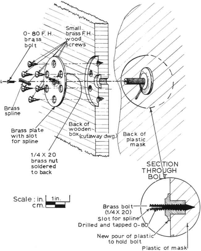
SINCE THE CAUSE of the breakage of the mask had been the previous poor mounting into its box, it was decided to devise a new, more secure mounting method. These operations were again tested first on the test piece before being used on the mask; here we will describe only the mask. One thing that we found out in working on the test piece was that the Clearcast had considerable shrinkage when poured in thick sections; any holes to be filled with Clearcast should be overfilled. A bolt was mounted in a hole in the test piece and, after prolonged setting, the bolt was so well adhered that hammering on it would not remove it. Instead, the test piece broke along the mended fracture line when the bolt was very heavily hit. We decided to adhere a �″ brass bolt to the back of the mask. This would protrude through the back of the box and be secured by a round mounting plate with a nut in the center which would thread onto the brass bolt (Figure 8). The mounting plate would then have holes for wood screws so that it could not rotate in the back of the box and so that it would be adequately held there. A small brass spline would go across the bolt where it protruded from the mounting plate to stop rotation of the mask and to hold the mask, nut, and mounting plate in register. The back of the box would be routed out to receive the mounting plate so that the entire back of the assembly could fit flush to the wall.
Fig. 8.
Detail of mounting method.
 |
The interior hole in the mask for mounting was cleaned out and polished carefully. The hole was then filled with dental impression material (Alginate), which was removed after setting for one minute and a plaster positive made from the impression. The plaster positive was then sectioned so that the end of the brass bolt could be contoured to fit the hole exactly (Fig. 9). Both the interior cavity and the bolt were carefully polished. The bolt was then inserted into the hole and Clearcast poured around it; a wax dam had been built around the hole so that it could be slightly overfilled. After setting for a week the resin was hard enough so that the wax could be removed. The resin was then tooled down to the correct shape and polished.
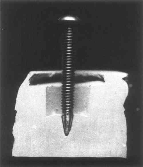
Fig. 9.
The attachment bolt, cut to fit the mold of the interior cavity.
 |
The box was drilled with a number F drill (.257 inches) so that a little clearance would be allowed for the �″ (.250″) bolt. The back of the box was then milled to receive the plate. The mask was inserted into the front of the box, and the plate and nut, which had been soldered together, were screwed on from the back until they were flush. Positions for the wood screws were marked and the position of the spline was marked on the plate. The assembly was taken apart, the spline hole milled out, the spline made to fit, and a small (0–80) flat-head brass machine screw set through the spline into a threaded hole in the center of the �″ bolt (Fig. 10). This would hold the spline in place in its hole so that it could then hold the bolt in position in the mounting plate. After testing the entire assembly for fit, everything was polished and lacquered with Incralac, a methacrylate lacquer formulated with benzotriazole, especially designed to slow corrosion of copper alloys. The milled hole in the back of the box was painted with a mixture of Magna copolymer paint and dammar varnish, to give a black shine to the edges. The entire unit was then reassembled, the box polished with tissue, and the object photographed in its finished state (Fig. 11).
Fig. 10.
The completed new attachment; oblique view from the back.
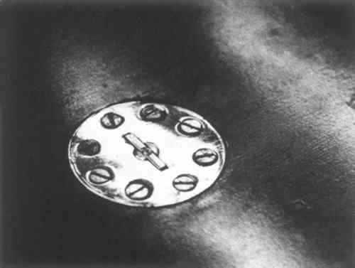 |
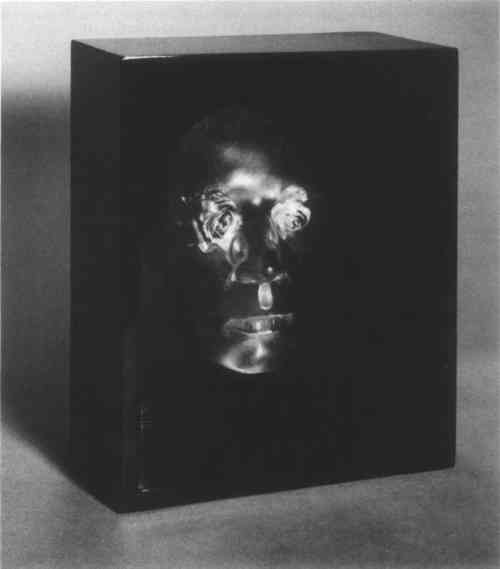
Fig. 11.
The mask after repair and remounting.
 |
|