THE FEASIBILITY OF USING THERMOGRAPHY TO DETECT SUBSURFACE VOIDS IN PAINTED WOODEN PANELSBRUCE F. MILLER
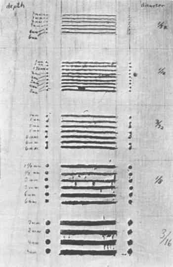
3 EXPERIMENTAL PROCEDURES AND RESULTSAn essential part of the research was the use of test panels that contained areas of simulated cleavage and worm tunneling. By comparing the known construction of the panels with the thermographic results, the feasibility of the technique could be established for known conditions. Although a number of test panels were constructed and analyzed thermographically for the original research, the space limitations of this paper prohibit the description of more than two of the test panels and their associated thermographic analyses. Test panel D-4 was designed to determine whether or not thermography could detect voids within a wooden support (simulating worm tunneling) and what the resolution of the instrument is
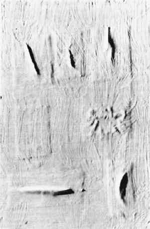
The thermographic studies of this panel made use of two heating techniques. The first technique was to suspend the panel from a steel frame 20″ in front of the radiometer and heat surface of the panel for ten seconds with a 250 watt infrared heat lamp. Figure 1a is a thermogram of the panel made ten seconds after the brief heating was completed. This thermogram shows all five groups of voids but they are poorly distinguished. Although the top group of voids, that with the narrowest grooves, does not show up well in this figure, it was discernible on the original and was slightly more apparent in other thermocouples made at the same time. The other heating method was to heat the panel evenly from the reverse. The heat lamp provided too little radiation to heat the entire panel from the reverse in a reasonable period of time. The only other source of even heating available in the hospital was a stream of hot air produced by an x-ray processing machine operating in an adjacent room. The temperature of this air was approximately 90�F (32�C). Figure 1b is a thermogram of the panel made one minute after the panel was removed from this source of heat. With this heating method much better resolution was obtained. Although the group of smallest voids is not at all visible, the individual grooves and adjacent holes can be differentiated in the last two groups. Thus, by heating the panel from the reverse, and with an object-radiometer distance of 20″, individual voids as small as 1/8″ in diameter could be resolved. The depths of the grooves, which ranged from 1 mm to 6 mm, did not affect their detectability. Panel D-1 was designed to simulate cleavage between the support and ground layer. To simulate such cleavage, patches of kraft paper were saturated with hide glue and adhered to a wood panel in such a manner that the paper was “tented” in the center of each patch. When the glue dried, six irregularly shaped oids had been produced beneath the paper patches. Gesso was applied over the panel and paper patches, and the dry gesso was coated with resin as well as was panel D-4. Figure 2b is a raking light photograph of the finished panel, and Figure 1c is a thermogram of the panel made one minute after the panel was removed from the flow of hot air that had heated it from the reverse. The sensitivity range of this thermogram was 4�C. The thermogram in Figure 1d was made one minute after Figure 1c, with a sensitivity range of 2�C. The dark images on the thermograms represent cool areas on the surface of the panel produced by the pockets of cleavage. Although the voids in this panel were apparent by visual examination and were also detectible by sounding, this experiment does indicated that thermography is capable of detecting simulated pockets of cleavage between the support and ground layers.
Another experiment was carried out to determine whether thermography could detect voids not directly beneath the gesso layer but deeper within the wood support. It was found that such voids are not readily detectible through thermographic analysis. This may be an advantage of thermographic analysis since only the most serious voids, those immediately beneath the paint and ground layers, are detectible. Anyone familiar with methods of infrared analysis is aware of the fact that different substances emit varying amounts of infrared radiation depending on their chemical composition, physical state, and other factors. This means that one object may emit more infrared radiation than another object even though both objects are at the same temperature. The amount of infrared radiation emitted by a substance is termed its emissivity.6 Large variations in emissivity might complicate the technique of detecting voids within panel paintings. It is possible that a small patch of paint with a high emissivity when surrounded To study this problem a number of experiments were carried out. First it was determined that artist's paints do indeed vary considerably in their infrared emissions. It was then determined that various varnishes, both natural and synthetic, have high emissivities. By applying strips of various varnishes over patches of oil paints with both high and low emissivities and studying this construction thermographically, it was determined that most surface coatings, especially dammar, mastic, and acrylic resins, have sufficiently high emissivities to mask or equalize variations in emissivity caused by pigments. In the electronics industry surface coatings have been applied to electronic components to equalize emissivity variations as large as 50:1.7 Thus if a painting contains a surface coating, emissivity variations will probably not be of great concern in void detection studies. From the experimental evidence it is apparent that thermography is a feasible technique for detecting subsurface voids in painted wooden panels. Individual voids beneath the gesso as small as 1/8″ in diameter were resolved and smaller voids were discernible when |