Design and Construction of a Support for a Folding Fan
by Holly MaxsonThe conservation treatment of this 18th C. French gentleman's fan will not be the focus of today's presentation. Rather, the challenge of creating a safe and unobtrusive support for its exhibition and storage after its stabilization is the topic of this brief talk.
I'd like to use Diagram A below to establish the standard terminology commonly used in describing the parts of a typical folding fan.
Starting at the base, the rivet is a pin which provides the structural pivot point for the folding fan. The rivet is inserted through the head of the sticks. The two outermost sticks are called the guards, and are of a sturdier construction in order to protect the fan while folded. As the sticks narrow and enter the leaf, they are called slips or ribs. The flexible fabric, paper or vellum which is used to join and cover the framework of slips is known as the mount or fan leaf.
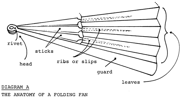
Diagram A. The Anatomy of a Folding Fan
As you can see, the structural strength of the fan is in the head, where the sticks are thickest and are stacked on the rivet, while the weakest structural areas are the folds in the paper leaf.
This fragile three-dimensionality, combined with the double-sided decoration, posed the greatest challenges in the design process. Additionally, I sought a design which would be:
- constructed of archivally safe materials
- unobtrusive as a display element
- capable of being displayed vertically or horizontally, and
- allow viewing without further handling or manipulation of the artifact.
The construction of the final support design is outlined in the following steps with several diagrams to clarify the structure as it is assembled.
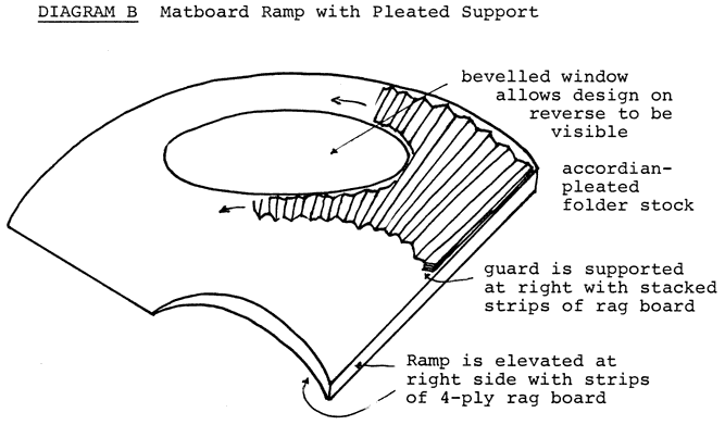
- First, the fan was opened just far enough to show the design to advantage without causing additional stress to the folds. The perimeter of the fan was traced lightly on a 4-ply sheet of acid-free ragboard. The ragboard was cut so that the top of the fan leaf would extend slightly beyond the upper edge of the support. A graceful curve was cut in the lower edge which echoes the curve of the fan and sweeps in an arc towards the head of the right guard. The purpose for this curve will become clearer as I go on.
- Maintaining the same extension, the fan was carefully turned over and the painted design on the reverse of the fan leaf was measured. A bevelled oval window was marked and cut in the ragboard support.
- Because the sticks and topmost guard gradually increase in height towards the right of the fan, additional support was required. The thickness of the closed fan (up to the underside of the topmost guard) was measured to determine the height of the slope required to support the gradually increasing height of the sticks. A long rectangular piece of matboard was cut and adhered beneath the right edge of the fan-shaped ragboard to establish the slope of the ramp. A tapered wedge of ragboard was then adhered along the lower curved cut to complete the ramp. (Diagram B)
- A sheet of flexible, acid-free, 10 point folder stock was
selected as a suitable material for the next step. The fan leaf and
dimensions of the folds were measured and the measurements
transferred to the sheet of folder stock. The folds were scored with
a bone folder and the folder stock creased to create an
accordian-like support for the fan leaf. The pleated support was
placed on the ramp and the oval window traced and cut so that it
matched the bevelled opening already cut in the ragboard support.
(Diagram B)
Diagram B. Matboard Ramp with Pleated Support
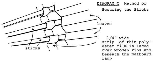
- The pleated support was then positioned on the ragboard ramp and
was secured along each of the depressed folds at two locations above
and below the oval window. A single running stitch of linen thread
was passed through small perforations and knotted on the underside
of the ramp
Diagram C. Method of Securing the Sticks
- The fan was placed in position on the pleated ramp and ¼"
notations were made to either side of each stick just below the fan
leaf. The fan was removed and slits were made with a scalpel through
the matboard ramp at the marks. A ¼" strip of polyester film
was laced over each stick and then beneath the ragboard ramp, gently
securing the framework with slight tension. (Diagram
C)
Diagram D1. Attachment of fan leaf as seen from top edge
See Diagram D2 below
Diagram D2. Closeup of a single hinge at top edge of fan leaf.
- An additional precaution was taken to attach the fan to the pleated support along the top edge. Tiny hinges of Japanese paper and wheat starch paste were used about every third pleat. These were applied with the fold of the hinge towards the depressed fold of the leaf to permit a certain amount of flexing of the fan leaf along the tented folds. The position of these small hinges was marked on the support so that caution would be exercised if the fan were ever removed from its mount. (Diagrams D1 and D2)
- Ribs of layered matboard were attached with double-sided tape to
the underside of the ramp to prevent warpage or sagging of the ramp.
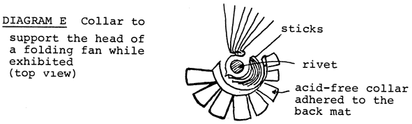
Diagram E. Collar to support the head of a folding fan while exhibited(top view)
- A small collar was fashioned from folder stock to provide additional support for the head of the fan if stored or displayed in an upright position. This was done by measuring half the thickness of the closed fan on a small rectangular piece of folder stock. Beyond this fold line, gores were cut at ¼" intervals and the collar was folded and curved. The collar was positioned beneath the head of the fan and was adhered to the ragboard mount with PVA adhesive. (Diagram E)
- A fan-shaped window mat was cut from 4-ply, acid-free mat board.
An infrastructure was constructed of acid-free corrugated panels and
short lengths of hollow Plexiglas tubing to elevate the mat window
above the fan surface. Strips of mat board were adhered with PVA
beneath the window mat to create a shadow box effect.
Diagram F. Cross section of sealed housing
- Finally, sheets of ultraviolet filtering Plexiglas were placed on either side of the matted fan and the edges of the package were secured with clear polyester film tape. This sealed package provides a barrier against airborn pollutants as well as rapid fluctuations in temperature and relative humidity. (Diagram F)


Every three-dimensional paper artifact has its own idiosyncrasies and presents challenges for curators and conservators. I hope that this exhibition/storage system will inspire other innovative designs. The advantage of this particular housing is its suitability for both temporary exhibition and permanent storage. The fan need not be removed for either situation. If project goals are established at the outset, simple techniques and commonly available materials can be used to solve the design problems in the most expedient, uncomplicated, and attractive manner.
I would like to acknowledge the entire staff of the Conservation Center for Art and Historic Artifacts for their helpful and imaginative ideas during the design of the support, but especially to thank Elizabeth Schulte, Supervising Conservator; Johnny Irizarry, whose expertise helped make the final structure a work of art; and Maria Holden, for her willingness to stand in for me today to present this lecture.
Holly MaxsonPrivate Conservator
Philadelphia, PA