THE DE-ELECTRIFICATION AND RE-ELECTRIFICATION OF HISTORIC LIGHTING FIXTURES AT WINTERTHUR MUSEUMBEVERLY N. PERKINS
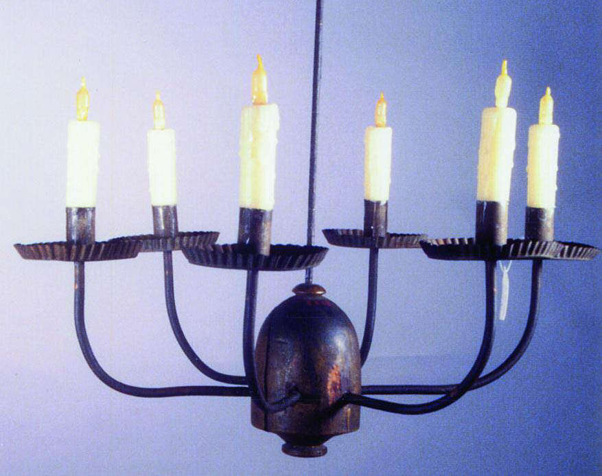
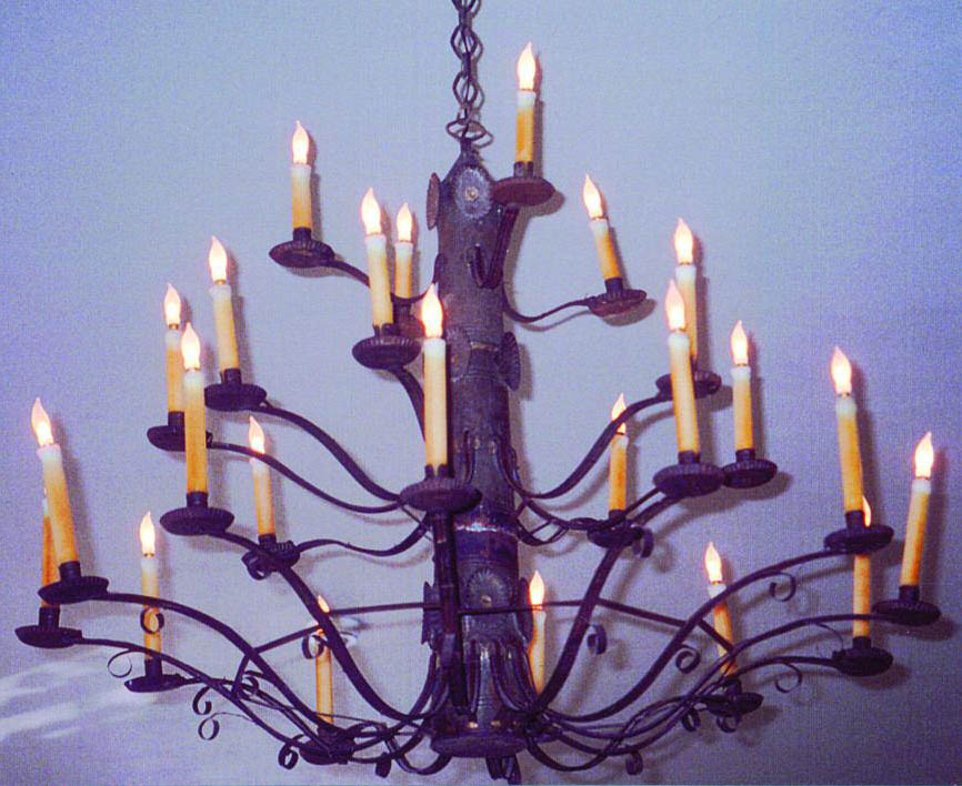
4 RE-ELECTRIFICATIONThe conservators at Winterthur were fortunate to be able to work with Richard Golon, a licensed electrician on staff at Winterthur. Staff members of Bayou Bend Collection and Gardens, Museum of Fine Arts, Houston, provided Winterthur with valuable information on the methods they had used to install Elcanco candles in modern lighting fixtures throughout their collections. However, the electrification of such a large number of historic lighting fixtures Many electric candles are available today. Most of the electric candles are obviously electric, with bright bulbs, plastic shafts, and large electrical cords. The desired features for the project included a realisticlooking candle and flame bulb and an electrical cord that would be as thin as possible and still be safe. The candle chosen for the project uses a low-wattage Handmade Candlewick Bulb manufactured by Elcanco, Ltd. (fig. 5, see page 450). The light level from a Candlewick bulb is approximately 1 footcandle. This light level is lower than that from the electric candles formerly used in the lighting fixtures (fig. 6, see page 450).
Light emitted by an Elcanco candle is very similar in intensity and color to that of a burning wax candle. The Elcanco system uses 6 volt candles with 6 watt incandescent bulbs. The Elcanco candle is a mixture of approximately 50 percent microcrystalline wax and 50 percent beeswax (Winterthur 1996). Elcanco manufactures candles to any width or height specification. The candles come in either beeswax color or a lighter ivory color. The wire color options are white, black, brown, golden clear, or silvery clear. The wire is easily painted with Liquitex acrylic emulsion tube paints (fig. 7, see page 450). The cost of the candles depends on the type of candle and the amount ordered.
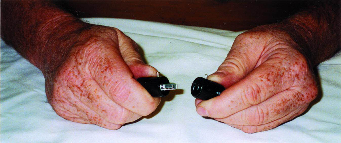
State and federal codes allow the use of 22 gauge wire when a low voltage system with a low wattage bulb is used. The 22 gauge wire has a smaller diameter than the 18 gauge wire found on most modern commercial lighting fixtures and is therefore easier to disguise. The plastic used for commercially available electrical cords is typically a form of PVC (Winterthur 1996). A great deal of consideration was given to the fact that re-electrification would mean placing PVC next to collections materials. Fortunately, Winterthur's collection contained many historic lighting fixtures with decades-old PVC electrical cords. The objects that had been polished, coated, and electrified with PVC wiring in the 1970s were examined. No evidence of corrosion caused by the PVC electrical cords could be found. Although it would have been preferable to use a nonchloride plastic as an alternative to PVC-coated electrical wire, research determined that the cost of developing and manufacturing alternative coatings for the electrical wires would be exorbitant. All metal surfaces that would come into contact with the electrical cord or the candle were coated with Agateen no. 27 cellulose nitrate lacquer. According to UL code, where an electrical cord is placed next to a potentially sharp edge, it must be reinforced with heat-shrink tubing. The precaution of covering the cord with heat-shrink tubing is taken to protect the cord from abrasion due to vibration over time. The heat-shrink tubing must extend .5 in. (1.25 cm) beyond each side of the potentially sharp edge. 3M heat-shrink tubing is a cross-linked polyolefin plastic available in different diameters (Winterthur 1997). The tubing was cut to the desired length, slipped onto the relevant section of electrical cord, and warmed with a hot air gun until it conformed to the cord. Transformers are used to step down the building's electrical current in order to accommodate the low voltage system. The transformers, which were approved by UL, will accommodate up to six candles. The transformers are concealed in accessible panels in the ceilings, walls, and built-in units at the floorboards. Each candle, or grouping of six candles in the case of multiple-candle chandeliers, received a fuse. Hanging fixtures received in-line fuses, and all other fixtures received fused plugs. Due to the use of six-volt transformers to convert conventional voltage to the lower voltage necessary for this lighting system, the electrical cords of the lighting fixtures did not end in the usual twopronged plug. Had the wires been attached to the transformers, movement of the objects would require cutting the electrical cord. When appropriate, interlocking Jones plugs were used to ensure easy object movement (fig. 8, see page 451). One-half of the Jones plug is soldered onto the cord of the fixture. The other half of the Jones plug is soldered onto the
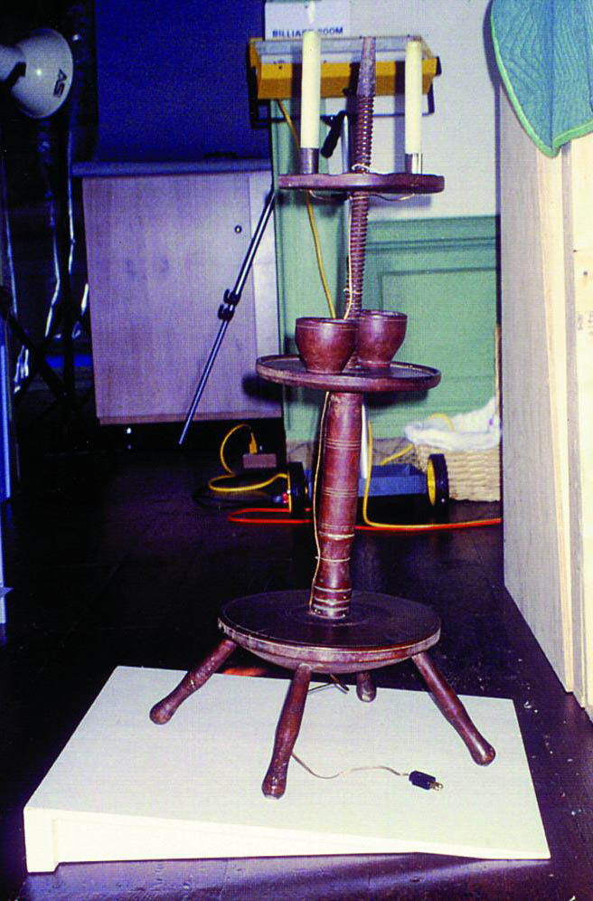
UL testing procedure for a newly manufactured lamp involves placing the lamp on an 8� incline and striking it with a specific weight ball swung as a pendulum from a specific height (UL 2002). If the lamp falls over, it is not approved by UL. If the lamp remains stable, it is approved and a metal tag is affixed to the lamp. This procedure obviously has some major drawbacks if applied to historic lighting fixtures. A modified version of the UL stability test was developed by Winterthur under the supervision of UL. Two wooden wedge-shaped platforms were built, each of which would provide an 8� incline. A small platform (8 � 8 in. [20 � 20 cm]) was built to enable testing of objects such as candlesticks, small lamps, and candelabra. A second platform (2 � 2 ft. [60 � 60 cm]) was used to test larger fixtures and candlestands. The test involved placing a lighting fixture on the incline (fig. 9, see page 451). The object was not hit with a ball but was released from the conservator's hands just long enough to ensure that it was stable. The objects were tested with candles in place due to the amount of weight that candles added to the top of the object. If the object proved to be stable, it was placed back into the collection. No metal tags were affixed to the objects.
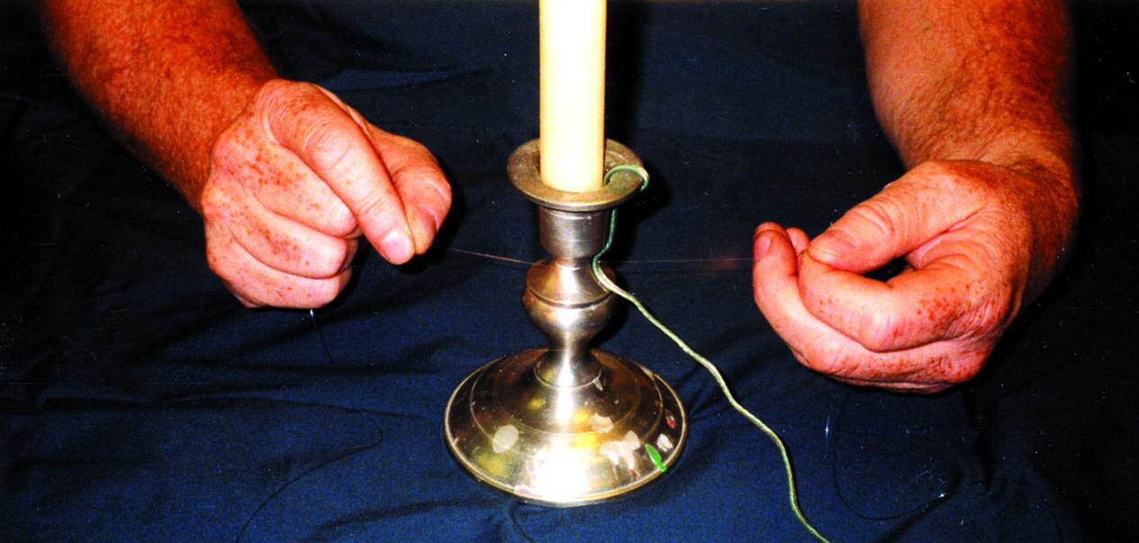
The old adhesives used to attach the electrical cords had caused damage to a variety of surfaces. This factor alone would have been enough to eliminate adhesives for use in attaching the electrical cords. Because it was felt that Paraloid B-72 might be safe to use with some surfaces and strong enough to hold the electrical cord in place, mock-ups were carried out using Paraloid B-72. The adhesive proved to be extremely difficult to hide, time consuming to use, and irreversible without removing the protective coating on metal objects. There is a danger that adhesive or its solvent might affect the plastic of the cord, eventually exposing the electrical wiring. Adhesive would have been safe to use on very few of the objects' surfaces. The new electrical cords were attached by tying with nylon monofilament fishing line (fig. 10, see page 451).
|