THE DE-ELECTRIFICATION AND RE-ELECTRIFICATION OF HISTORIC LIGHTING FIXTURES AT WINTERTHUR MUSEUMBEVERLY N. PERKINS
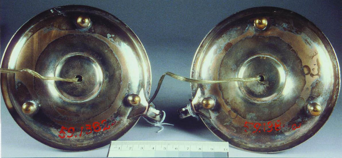
2 DE-ELECTRIFICATIONThe electrification of the lighting fixtures had occurred over many decades. Numerous techniques and unknown materials had been used to simulate candleand gaslight. Some electric candles were hollow plastic sleeves containing metal rods. Many others consisted of various unknown waxes molded around a tube that served as a conduit for the electrical wire. Many of the candles were held in place with an unknown hard wax. The hard wax was used to keep the candle upright when the bottom of the candle was smaller than the candle cup. Candles held in place with hard wax were usually fairly easy to remove. If the candle cup was metal, it was barely warmed with a hair dryer to facilitate the removal of the wax remaining in the cup. Warming the candle cup was very quick and less toxic than using solvents. However, the original application of hot molten wax had caused some ceramic and glass candle cups to break. These candle cups could not be warmed due to the danger of further weakening the structure. Also, the process of warming the hard wax in a ceramic or glass candle cup could create a vacuum when the candle and the waxy sludge were lifted out of the candle cup. Warming or soaking a wooden object in order to remove a tenacious candle was not an option due to the potential for irreversible damage. In these difficult cases, the candle was removed by carving away the hard wax with scalpel blades and wooden ceramicists' tools. In most instances, the electrical cord had been attached to the surface of the lighting fixture with adhesive. There was evidence that the old adhesives had caused accelerated corrosion of the metal surfaces. The old adhesives had degraded over time, and fluctuations in relative humidity had caused them to swell and shrink. Areas of adhesive were lifting, often pulling up delicate paint or gilt surfaces. At times it was necessary to carry out surface consolidation before the adhesive could be removed. Metal feet had been soldered onto many of the metal lighting fixtures (fig. 2, see page 449). The new feet raised the fixture up, leaving a space through which the electrical cord could pass. Metal loops and hooks had been soldered onto the back of some lighting fixtures. These loops were used to help guide the electrical cord down the back of the object.
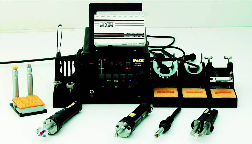
Nonoriginal elements that had been attached to the object in order to facilitate electrification were removed whenever possible. A PACE MBT 250A Desoldering Tool was used to remove the nonoriginal soldered elements (fig. 3, see page 449). The temperature range of the MBT 250A is 100–900�F.
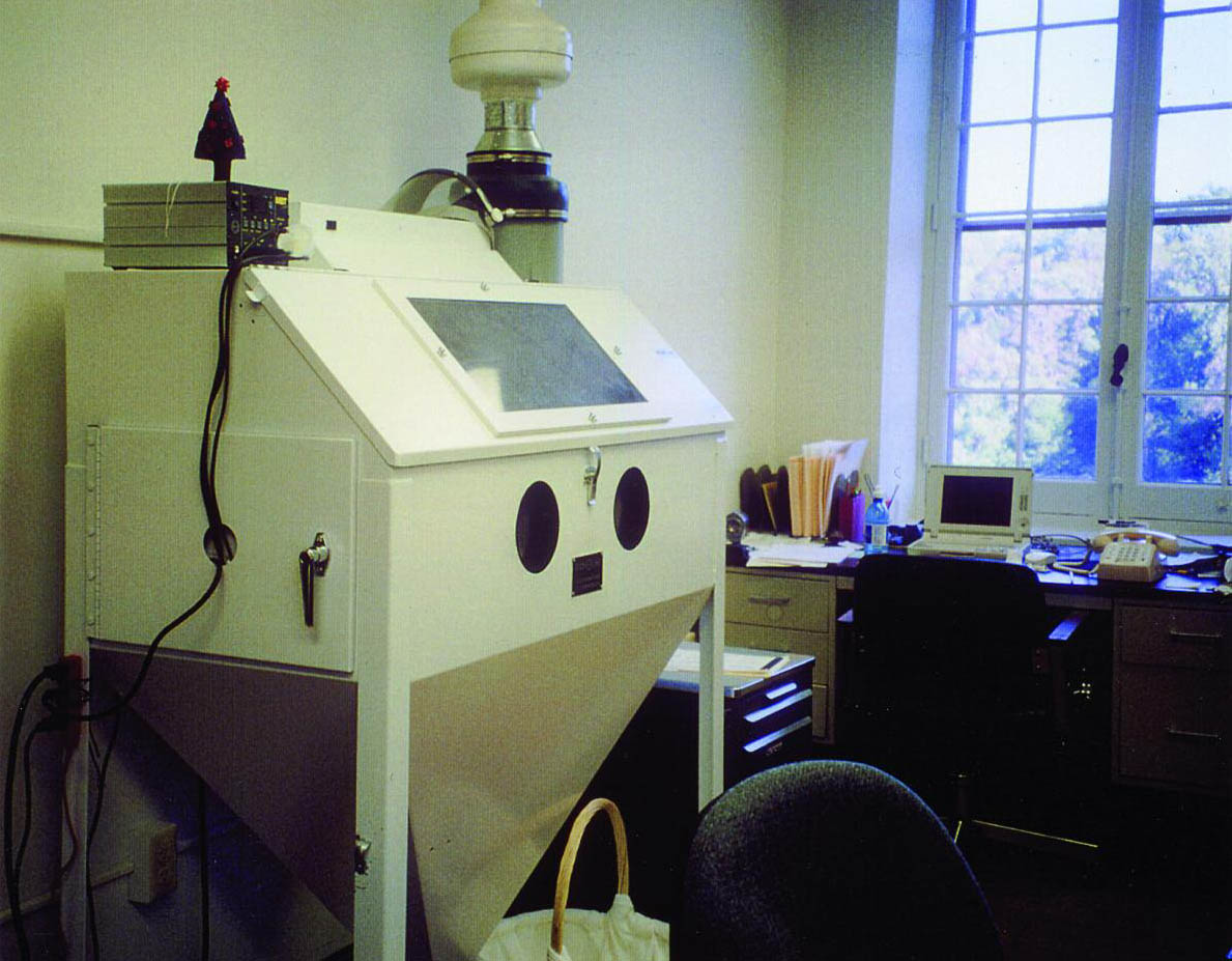
The MBT 250A is a small unit with a hand tool attachment similar to a Dremel Tool. The MBT 250A works very quickly and safely. The solder is collected in a small suction chamber attached to the tool. One difficulty in working with the desoldering tool is that the tip of the tool must be kept clean in order for it to work properly. The desoldering tool was used to melt the majority of the solder. A layer of the solder was left on the object to ensure that the desoldering tool did not come into contact with the original surface. Remaining solder was removed by abrading with a Dremel Tool, cutting with a scalpel blade, and finally abrading with fine grit abrasive paper. The risk of damaging an object through the application of heat was considered at some length. Applying heat to an object might cause areas of lowtemperature solder to fail. Solder failure might result in elements' becoming detached or loosened. Heat might also alter the surface treatment, changing the appearance of the object. Evidence of manufacture might also be lost through the application of heat. For objects susceptible to changes from the application of heat, any damage that was going to occur had probably occurred when the nonoriginal metal pieces had been soldered on during the electrification process. It was felt that the desoldering tool transferred much less heat to the object, and for a shorter period of time, than had occurred during the original soldering. No evidence of adverse affects to an object from the heat of the desoldering tool was observed during the project. Working with lead solder could create health risks; therefore, precautions were taken to minimize the risk of contamination due to the presence of lead in the solder. Desoldering activities were carried out within a sealed-exhaust glove box (fig. 4, see page 450). Although it was not an Occupational Safety and Health Administration (OSHA) requirement, an industrial hygienist examined working procedures and sampled various surfaces in the laboratory space. The samples indicated that the danger from lead contamination was negligible. Staff members were given blood tests at the beginning of the project in order to have baseline information in the event that a health issue arose. As the danger from lead contamination was negligible and the staff remained healthy, no further blood testing or monitoring was carried out.
|