THE DE-ELECTRIFICATION AND RE-ELECTRIFICATION OF HISTORIC LIGHTING FIXTURES AT WINTERTHUR MUSEUMBEVERLY N. PERKINS
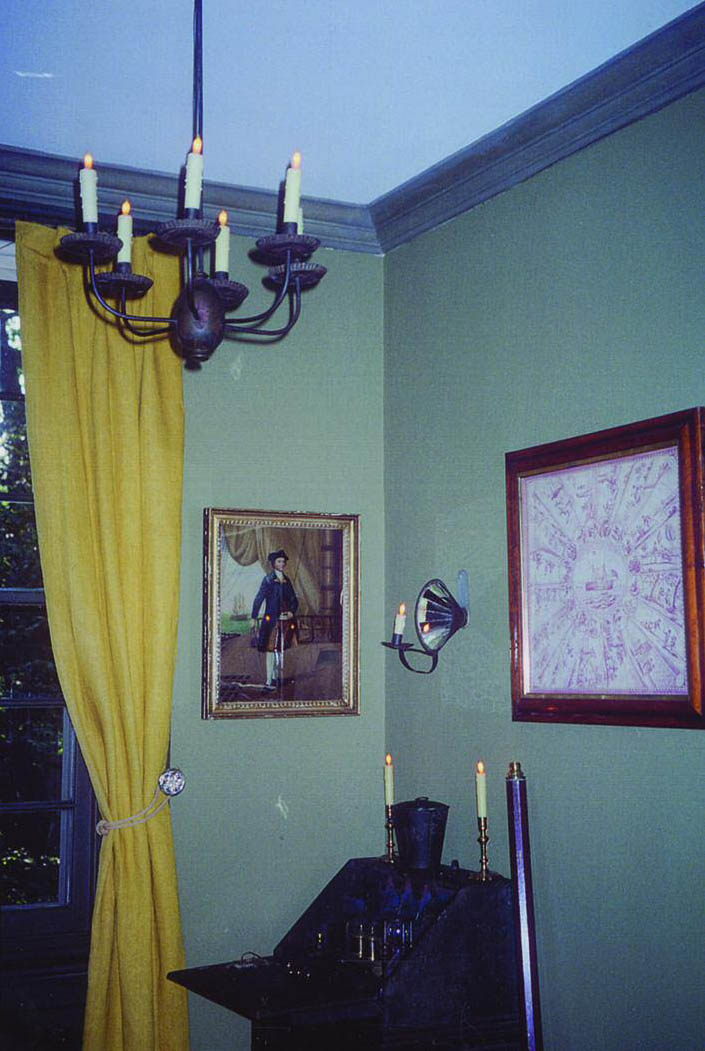
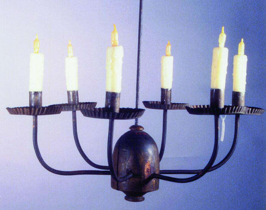
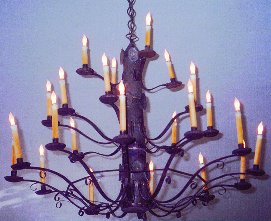
ABSTRACT—New electrical systems were installed in 175 period rooms of Winterthur Museum. This project provided an opportunity for the Conservation Department to de-electrify and conserve the collection of more than 1,000 historic lighting fixtures. Selected objects were re-electrified in an attempt to minimize the danger to the object and maximize the aesthetic quality of simulated candleand gaslight. TITRE—L'enl�vement et la repose des circuits �lectriques sur des luminaires historiques au Winterthur Museum (mus�e Winterthur). R�SUM�—De nouveaux circuits �lectriques ont �t� install�s dans 175 salles d'�poque au Winterthur Museum. Ce projet a donn� l'occasion au service de la restauration d'enlever les syst�mes �lectriques et de restaurer une collection de plus de mille luminaires historiques. Certains appareils ont �t� �quip�s de nouveaux syst�mes �lectriques afin de r�duire le danger de court-circuit et dommage � l'objet, et afin de simuler les qualit�s particuli�res de l'�clairage fourni par les bougies ou les lampes � p�trole. TITULO—La deselectrificaci�n y electrificaci�n de l�mparas hist�ricas en el Winterthur Museum (Museo de Winterthur). RESUMEN—Nuevos sistemas el�ctricos fueron instalados en 175 cuartos hist�ricos en el Winterthur Museum. Este proyecto dio la oportunidad al Departamento de Conservaci�n de deselectrificar mas de 1.000 l�mparas hist�ricas. Algunos objetos seleccionados fueron reelectrificados para tratar de minimizar el peligro al objeto y maximizar la calidad est�tica de la luz que simula una vela o una l�mpara de gas. T�TULO—A desativa��o e a re-eletrifica��o de lumin�rias hist�ricas no Winterthur Museum (Museu de Winterthur). RESUMO—O Winterthur Museum instalou novos sistemas el�tricos em 175 salas tem�ticas. Este projeto criou uma oportunidade para o Departamento de Conserva��o desativar e conservar a cole��o de mais de 1.000 lumin�rias hist�ricas. Alguns objetos selecionados foram reeletrificados na tentativa de minimizar danos ao objeto e maximizar a qualidade est�tica da luz de vela e a g�s simuladas. 1 INTRODUCTIONWinterthur Museum upgraded all the electrical systems in the museum building. The electrical systems were aging, and, as they were installed over many decades, there was a lack of cohesion and uniformity among them. This large project offered an opportunity for the Conservation Department to carry out conservation treatments on many objects in the collections. Rooms were cleared of all collections materials before the electricians began work on the in-wall wiring. Because they are accessioned collection objects, all the historic lighting fixtures came through the conservation laboratory for examination, treatment, and, when necessary, re-electrification. A team consisting of a conservator, a conservation assistant, two technicians, and numerous interns concentrated their efforts solely on the treatment of the lighting fixtures. The treatment of the historic lighting fixtures took the better part of two years. Winterthur's collection contains more than 1,000 historic lighting fixtures. The collection consists of 17th-, 18th-, and 19th-century fixtures such as silver oil lamps, wooden candlestands, silver candlesticks, brass chandeliers, ceramic candelabra, painted iron lanterns, and iron and brass candlestands. A museum report explains that Henry Francis du Pont included lighting fixtures in his collection because of their historic importance and beauty and for the effect their light would add to the period atmosphere in the rooms (fig. 1, see page 449). In the 1920s he was attempting to replicate the appearance of natural candlelight in his own home by using electric bulbs that simulated flames. The use of electric candles in historic lighting fixtures was introduced into the rooms at Winterthur in 1929 when du Pont inherited the Winterthur house (Lamden and Kirschner 1995).
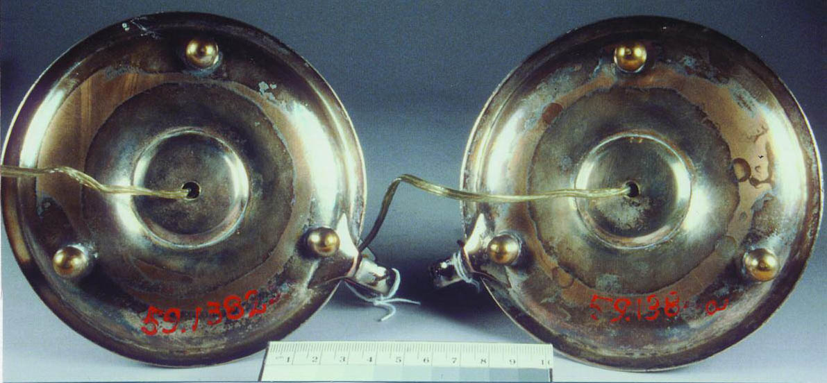
The electrification of lighting fixtures continued over the decades as du Pont built his collection. Some of the lighting fixtures were modified so that the electrical wires could be more easily hidden. Du Pont purchased some fixtures that were already modified for electricity. Other fixtures were electrified, at the request of du Pont, by his staff. Although it would not be within Winterthur's current policy to electrify an object that had not already been used as a source for lighting the collection, some of the objects were re-electrified in order to maintain du Pont's vision. An important aspect of the project was re-electrifying objects in a manner that would be unobtrusive, safe for the object, and safe in terms of electrical systems. Although the conservation treatments on the objects were varied and at times complex, they followed current standard practices and will not be presented in this paper. This project would not have succeeded without the team that was formed by the directors of three different divisions: Chief Conservator Gregory Landrey, Plant Engineer and Director of Facilities Services Michael S. Dixon, and Exhibitions Division Director Felice Jo Lamden. The three directors designed the timeline for the project, integrating the conservation component into the rewiring and lighting projects taking place simultaneously. The team of directors designed the budget for staffing, materials, and space renovations. By meeting regularly with relevant staff throughout the project, the team of directors facilitated the movement of objects and solved logistical problems. This team, along with Curator Donald Fennimore, carried out research on electric candles, even traveling to other venues to see lighting systems in place. 2 DE-ELECTRIFICATIONThe electrification of the lighting fixtures had occurred over many decades. Numerous techniques and unknown materials had been used to simulate candleand gaslight. Some electric candles were hollow plastic sleeves containing metal rods. Many others consisted of various unknown waxes molded around a tube that served as a conduit for the electrical wire. Many of the candles were held in place with an unknown hard wax. The hard wax was used to keep the candle upright when the bottom of the candle was smaller than the candle cup. Candles held in place with hard wax were usually fairly easy to remove. If the candle cup was metal, it was barely warmed with a hair dryer to facilitate the removal of the wax remaining in the cup. Warming the candle cup was very quick and less toxic than using solvents. However, the original application of hot molten wax had caused some ceramic and glass candle cups to break. These candle cups could not be warmed due to the danger of further weakening the structure. Also, the process of warming the hard wax in a ceramic or glass candle cup could create a vacuum when the candle and the waxy sludge were lifted out of the candle cup. Warming or soaking a wooden object in order to remove a tenacious candle was not an option due to the potential for irreversible damage. In these difficult cases, the candle was removed by carving away the hard wax with scalpel blades and wooden ceramicists' tools. In most instances, the electrical cord had been attached to the surface of the lighting fixture with adhesive. There was evidence that the old adhesives had caused accelerated corrosion of the metal surfaces. The old adhesives had degraded over time, and fluctuations in relative humidity had caused them to swell and shrink. Areas of adhesive were lifting, often pulling up delicate paint or gilt surfaces. At times it was necessary to carry out surface consolidation before the adhesive could be removed. Metal feet had been soldered onto many of the metal lighting fixtures (fig. 2, see page 449). The new feet raised the fixture up, leaving a space through which the electrical cord could pass. Metal loops and hooks had been soldered onto the back of some lighting fixtures. These loops were used to help guide the electrical cord down the back of the object.
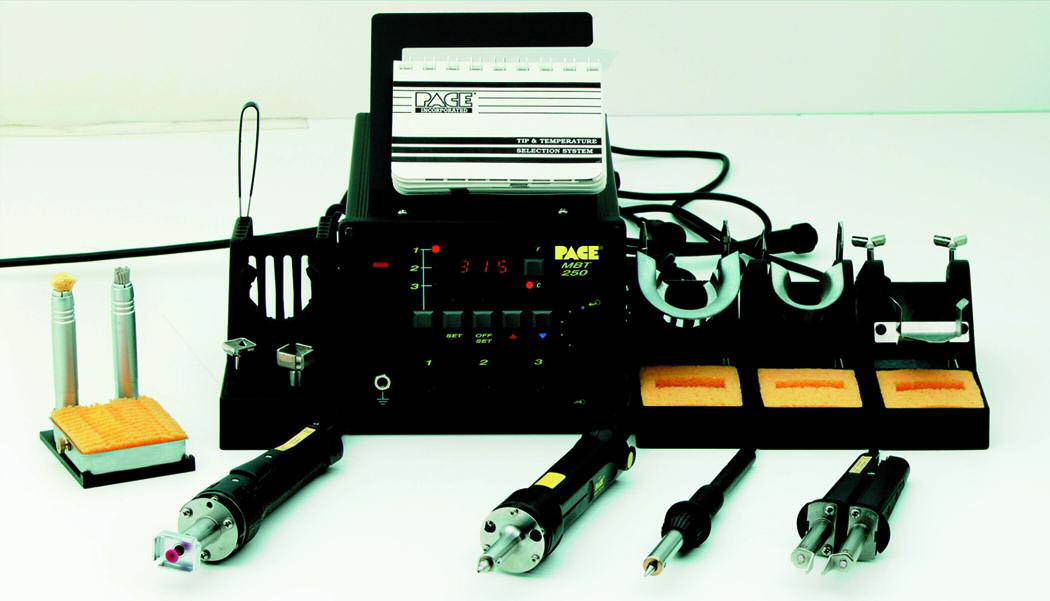
Nonoriginal elements that had been attached to the object in order to facilitate electrification were removed whenever possible. A PACE MBT 250A Desoldering Tool was used to remove the nonoriginal soldered elements (fig. 3, see page 449). The temperature range of the MBT 250A is 100–900�F.
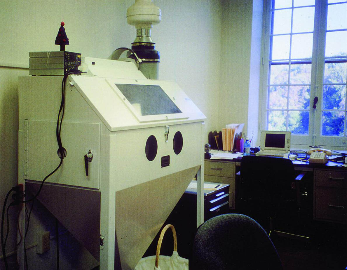
The MBT 250A is a small unit with a hand tool attachment similar to a Dremel Tool. The MBT 250A works very quickly and safely. The solder is collected in a small suction chamber attached to the tool. One difficulty in working with the desoldering tool is that the tip of the tool must be kept clean in order for it to work properly. The desoldering tool was used to melt the majority of the solder. A layer of the solder was left on the object to ensure that the desoldering tool did not come into contact with the original surface. Remaining solder was removed by abrading with a Dremel Tool, cutting with a scalpel blade, and finally abrading with fine grit abrasive paper. The risk of damaging an object through the application of heat was considered at some length. Applying heat to an object might cause areas of lowtemperature solder to fail. Solder failure might result in elements' becoming detached or loosened. Heat might also alter the surface treatment, changing the appearance of the object. Evidence of manufacture might also be lost through the application of heat. For objects susceptible to changes from the application of heat, any damage that was going to occur had probably occurred when the nonoriginal metal pieces had been soldered on during the electrification process. It was felt that the desoldering tool transferred much less heat to the object, and for a shorter period of time, than had occurred during the original soldering. No evidence of adverse affects to an object from the heat of the desoldering tool was observed during the project. Working with lead solder could create health risks; therefore, precautions were taken to minimize the risk of contamination due to the presence of lead in the solder. Desoldering activities were carried out within a sealed-exhaust glove box (fig. 4, see page 450). Although it was not an Occupational Safety and Health Administration (OSHA) requirement, an industrial hygienist examined working procedures and sampled various surfaces in the laboratory space. The samples indicated that the danger from lead contamination was negligible. Staff members were given blood tests at the beginning of the project in order to have baseline information in the event that a health issue arose. As the danger from lead contamination was negligible and the staff remained healthy, no further blood testing or monitoring was carried out.
3 THE USE OF AGATEEN LACQUERThe effectiveness and stability of Agateen Lacquer no. 27 (cellulose nitrate, used with thinner no. 1) became evident as lighting fixtures came into the laboratory for treatment. Most of the brass, silver, and silver plate lighting fixtures were polished and lacquered during the coating program that began at Winterthur in the early 1970s under the direction of conservator Don Heller (Heller 1983). Silver, silver plate, and brass objects that had been coated with Agateen Lacquer in the late 1970s still held a unified polish. The effectiveness of various coatings (including Agateen) in resisting the transmission of sulfide vapor is presented in a report submitted by Chandra Reedy (Reedy et al. 1998). The Agateen Lacquer appeared to have protected the metal surfaces from corrosion problems that could have been caused by years of proximity to polyvinyl chloride (PVC) wiring or beeswax candles. This finding was very important to the re-electrification project because PVC wiring and beeswax would, once again, be placed next to metal surfaces. The use of Agateen Lacquer no. 27 and thinner no. 1 was continued in the rewiring project because of Agateen's leveling properties when applied as a brush coat, the near invisibility of Agateen on the metal surface, and Agateen's evident success at protecting a polished surface. The solvent system used with Agateen Lacquer is very toxic and should be used with a ventilation system (Agate Lacquer 1986). 4 RE-ELECTRIFICATIONThe conservators at Winterthur were fortunate to be able to work with Richard Golon, a licensed electrician on staff at Winterthur. Staff members of Bayou Bend Collection and Gardens, Museum of Fine Arts, Houston, provided Winterthur with valuable information on the methods they had used to install Elcanco candles in modern lighting fixtures throughout their collections. However, the electrification of such a large number of historic lighting fixtures Many electric candles are available today. Most of the electric candles are obviously electric, with bright bulbs, plastic shafts, and large electrical cords. The desired features for the project included a realisticlooking candle and flame bulb and an electrical cord that would be as thin as possible and still be safe. The candle chosen for the project uses a low-wattage Handmade Candlewick Bulb manufactured by Elcanco, Ltd. (fig. 5, see page 450). The light level from a Candlewick bulb is approximately 1 footcandle. This light level is lower than that from the electric candles formerly used in the lighting fixtures (fig. 6, see page 450).
Light emitted by an Elcanco candle is very similar in intensity and color to that of a burning wax candle. The Elcanco system uses 6 volt candles with 6 watt incandescent bulbs. The Elcanco candle is a mixture of approximately 50 percent microcrystalline wax and 50 percent beeswax (Winterthur 1996). Elcanco manufactures candles to any width or height specification. The candles come in either beeswax color or a lighter ivory color. The wire color options are white, black, brown, golden clear, or silvery clear. The wire is easily painted with Liquitex acrylic emulsion tube paints (fig. 7, see page 450). The cost of the candles depends on the type of candle and the amount ordered.
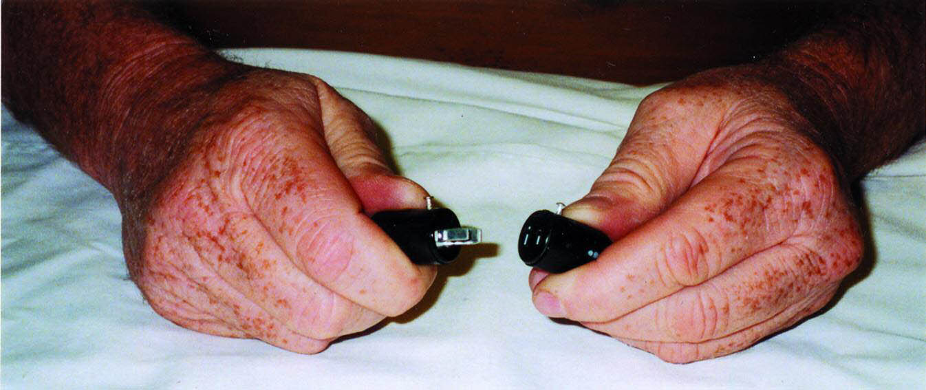
State and federal codes allow the use of 22 gauge wire when a low voltage system with a low wattage bulb is used. The 22 gauge wire has a smaller diameter than the 18 gauge wire found on most modern commercial lighting fixtures and is therefore easier to disguise. The plastic used for commercially available electrical cords is typically a form of PVC (Winterthur 1996). A great deal of consideration was given to the fact that re-electrification would mean placing PVC next to collections materials. Fortunately, Winterthur's collection contained many historic lighting fixtures with decades-old PVC electrical cords. The objects that had been polished, coated, and electrified with PVC wiring in the 1970s were examined. No evidence of corrosion caused by the PVC electrical cords could be found. Although it would have been preferable to use a nonchloride plastic as an alternative to PVC-coated electrical wire, research determined that the cost of developing and manufacturing alternative coatings for the electrical wires would be exorbitant. All metal surfaces that would come into contact with the electrical cord or the candle were coated with Agateen no. 27 cellulose nitrate lacquer. According to UL code, where an electrical cord is placed next to a potentially sharp edge, it must be reinforced with heat-shrink tubing. The precaution of covering the cord with heat-shrink tubing is taken to protect the cord from abrasion due to vibration over time. The heat-shrink tubing must extend .5 in. (1.25 cm) beyond each side of the potentially sharp edge. 3M heat-shrink tubing is a cross-linked polyolefin plastic available in different diameters (Winterthur 1997). The tubing was cut to the desired length, slipped onto the relevant section of electrical cord, and warmed with a hot air gun until it conformed to the cord. Transformers are used to step down the building's electrical current in order to accommodate the low voltage system. The transformers, which were approved by UL, will accommodate up to six candles. The transformers are concealed in accessible panels in the ceilings, walls, and built-in units at the floorboards. Each candle, or grouping of six candles in the case of multiple-candle chandeliers, received a fuse. Hanging fixtures received in-line fuses, and all other fixtures received fused plugs. Due to the use of six-volt transformers to convert conventional voltage to the lower voltage necessary for this lighting system, the electrical cords of the lighting fixtures did not end in the usual twopronged plug. Had the wires been attached to the transformers, movement of the objects would require cutting the electrical cord. When appropriate, interlocking Jones plugs were used to ensure easy object movement (fig. 8, see page 451). One-half of the Jones plug is soldered onto the cord of the fixture. The other half of the Jones plug is soldered onto the
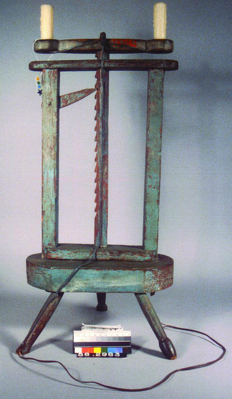
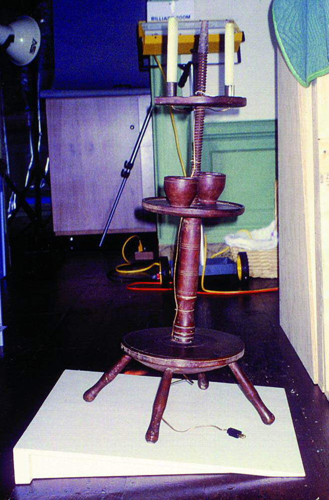
UL testing procedure for a newly manufactured lamp involves placing the lamp on an 8� incline and striking it with a specific weight ball swung as a pendulum from a specific height (UL 2002). If the lamp falls over, it is not approved by UL. If the lamp remains stable, it is approved and a metal tag is affixed to the lamp. This procedure obviously has some major drawbacks if applied to historic lighting fixtures. A modified version of the UL stability test was developed by Winterthur under the supervision of UL. Two wooden wedge-shaped platforms were built, each of which would provide an 8� incline. A small platform (8 � 8 in. [20 � 20 cm]) was built to enable testing of objects such as candlesticks, small lamps, and candelabra. A second platform (2 � 2 ft. [60 � 60 cm]) was used to test larger fixtures and candlestands. The test involved placing a lighting fixture on the incline (fig. 9, see page 451). The object was not hit with a ball but was released from the conservator's hands just long enough to ensure that it was stable. The objects were tested with candles in place due to the amount of weight that candles added to the top of the object. If the object proved to be stable, it was placed back into the collection. No metal tags were affixed to the objects.
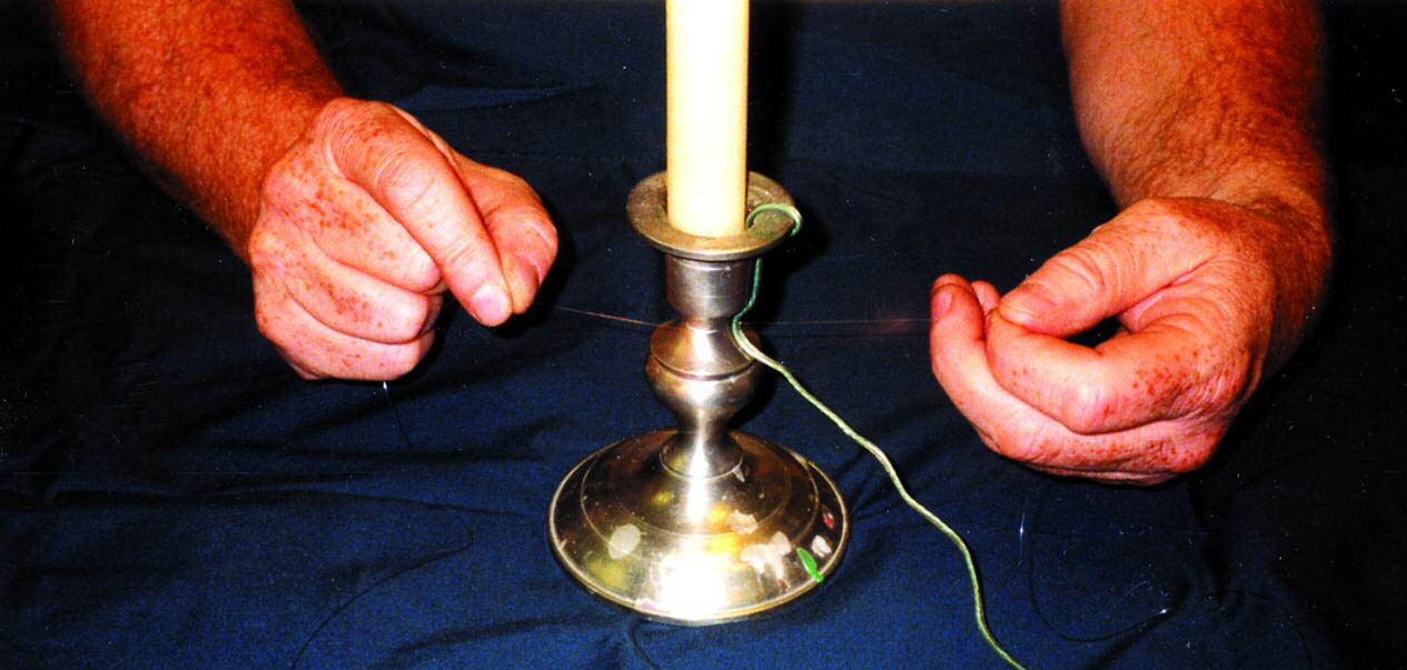
The old adhesives used to attach the electrical cords had caused damage to a variety of surfaces. This factor alone would have been enough to eliminate adhesives for use in attaching the electrical cords. Because it was felt that Paraloid B-72 might be safe to use with some surfaces and strong enough to hold the electrical cord in place, mock-ups were carried out using Paraloid B-72. The adhesive proved to be extremely difficult to hide, time consuming to use, and irreversible without removing the protective coating on metal objects. There is a danger that adhesive or its solvent might affect the plastic of the cord, eventually exposing the electrical wiring. Adhesive would have been safe to use on very few of the objects' surfaces. The new electrical cords were attached by tying with nylon monofilament fishing line (fig. 10, see page 451).
5 CONCLUSIONSIt is not within current Winterthur policy to electrify a collection object that has not already been used as a source of lighting for the collection. Collection objects should not be modified by drilled holes, applied soldered attachments, or adhesives on original surfaces in order to accommodate electrical wiring. The conservators at Winterthur were fortunate to be able to work with engineers, electricians, Underwriter Laboratories, and conservation colleagues on this project. It is hoped that the presentation of some of the systems that were developed in this manner might prove useful to others needing to re-electrify lighting fixtures. ACKNOWLEDGEMENTSThe author would like to thank Gregory Landrey, Michael S. Dixon, and Felice Jo Lamden for all the research they carried out before the project started and their constant support throughout the project. My thanks to Mary Jane Robinson, Veronica Domingo, and Chris Williams, who formed a talented conservation team. The input and support of curators Donald Fennimore, Patricia Halfpenny, and Wendy Cooper were invaluable, as was the work of Janice Carlson and Kate Duffy of the Winterthur Analytical Laboratory. A special thank-you to my husband, Dr. Randall A. Leisey, for his support of my working on one coast while living on the other. The following individuals contributed their invaluable assistance and insight: Ann Boulton, Herb Crossan, Karen Godwin, Richard Golon, Don Heller, Keith Jameson, Paul Koenig, Lisa Moberg, Steve Pine, Julie Randolph, Jason Rice, Julia Robinson, Rebecca Rudma, Sara Shpargel, and Emily Spivack. REFERENCESAgate Lacquer Co. 1986. Material safety data sheet NPCA 1–84. March 20. Long Island City, N. Y. Heller, D.1983. The coating of metal objects at Winterthur. AIC preprints, American Institute for Conservation 11th Annual Meeting, Baltimore. Washington, D. C.:AIC. 57–64. Lamden, F. J., and A.Kirschner. 1995. Museum lighting retrospective report. Winterthur Museum, Winterthur, Del. Reedy, C. L., R. A.Corbett, D. L.Long, R. E.Tatnall, and B. D.Krantz. 1998. Evaluation of three protective coatings for indoor silver artifacts. Objects Specialty Group postprints, American Institute for Conservation 27th Annual Meeting, St. Louis. Washington, D. C.:AIC. 6:41–69 UL. 2002. Portable electric lamp stability test, Standard 153. March 25. Underwriters Laboratories, Northbrook, Ill. Winterthur Museum Analytical Laboratory. 1996. Compositional information report request 3619. May 23. Winterthur Museum, Winterthur, Del. Winterthur Museum Analytical Laboratory. 1997. Compositional information report request 3703. March 27. Winterthur Museum, Winterthur, Del. SOURCES OF MATERIALSElectric candlesElcanco, Ltd. P.O. Box 682 Westford, Mass. 01886 Lacquer coating for metalsAgate Lacquer Co. 11-13 43d Rd. Long Island City, N.Y. 11101 Heat-shrink tubing, EP 3013M Co. 6801 River Place Blvd. Austin, Tex. 78726-9000 Desoldering tool and equipmentPACE, Inc. 9893 Brewers Court Laurel, Md. 29723 Paraloid B-72Rohm and Haas Co. Independence Mall West Philadelphia, Pa. 19105 AUTHOR INFORMATIONBEVERLY N. PERKINS holds an M.A., certificate of advanced study (C.A.S.) in conservation from Buffalo State College and an M.A. in art history from the University of Chicago. She is a fellow and former board member of AIC and Western Association for Art Conservation (WAAC). She is currently at the Balboa Art Conservation Center as the National Endowment for the Humanities–funded regional field service officer for the Western Region. Address: 37224 Huckaby Lane, Murrieta, Calif. 92562
 Section Index Section Index |