MANAGING CHANGE: THE ROLE OF DOCUMENTATION AND CONDITION SURVEY AT MESA VERDE NATIONAL PARKFRANK G. MATERO
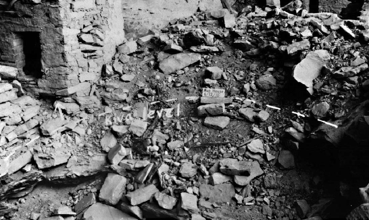
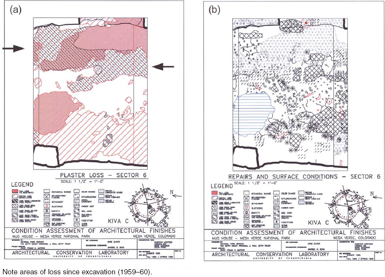
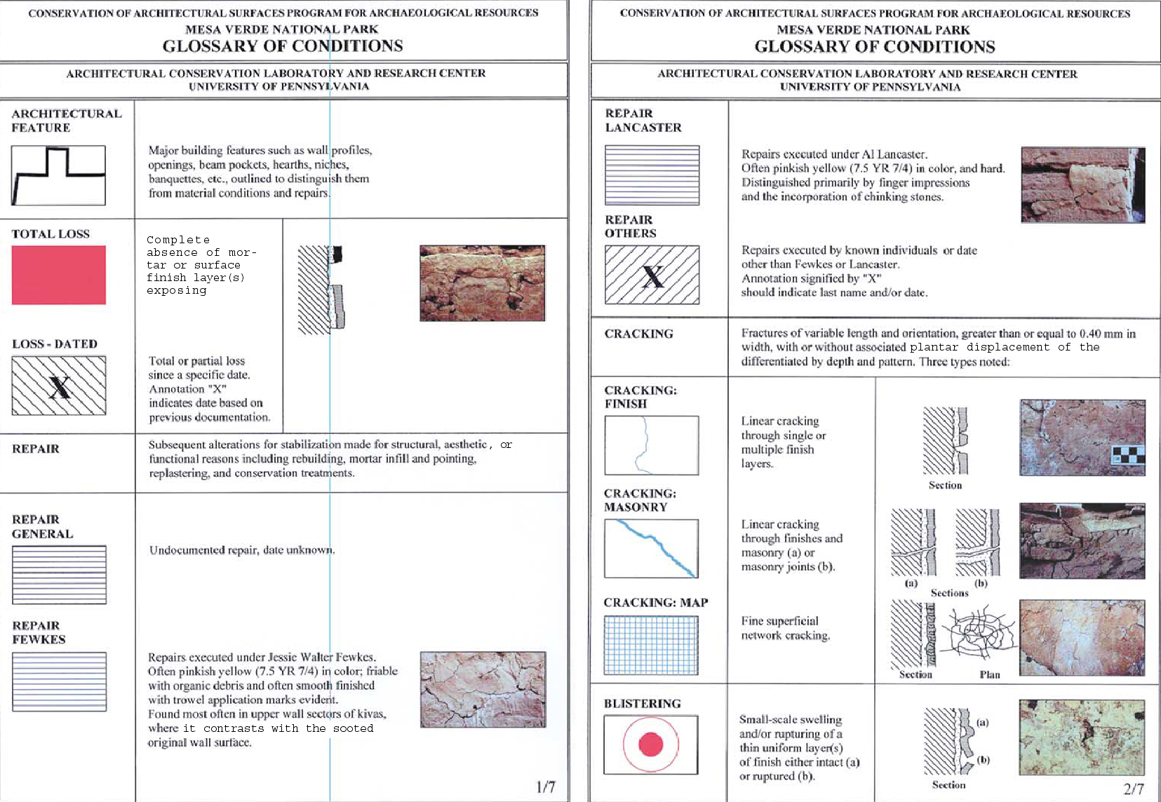
4 SUBTRACTIVE CONDITIONS4.1 LOSS/PARTIAL LOSSTotal loss is the final and ultimate stage of deterioration for surface finishes. It is the most extreme condition and obviously nonrecoverable; however, the careful recording of total and partial loss is a useful indicator of past and current patterns and trends, especially when datable through earlier photodocumentation. When viewed in conjunction with partial loss, active deterioration characterized by specific conditions such as detachment, delamination, and flaking can be understood as the preface to total loss. In Kiva C (and most other kivas), nearly all loss has occurred across the upper walls and along the upper quarter of the lower banquette walls (fig. 8, see page 61). This loss pattern is due to the overall vulnerability of these areas to weather exposure during occupation from roof leaks (prehistoric repairs are often found in the upper walls), after abandonment from associated roof collapse, and after excavation and rebuilding during stabilization. Early prestabilization photographs of Kiva C (1935) show masonry and roof collapse, exposed upper walls, and total plaster loss (fig. 9). The lower banquette walls—being concealed and possibly protected by fallen roof and debris—were observed in 1935 to be generally intact, a situation common for many kivas in cliff sites. A comparison of the extent of surviving plaster evident immediately after excavation and stabilization in 1959–60 to today overwhelmingly illustrates the loss of plaster that often results after excavation. At Kiva C more than 25% (surface area) of the existing plaster finishes recorded in 1960 was subsequently lost over the next 40 years of exposure, most of the loss occurring along the upper banquette.
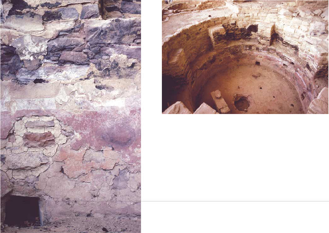
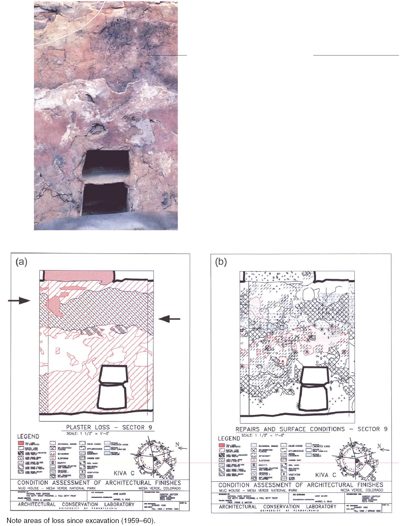
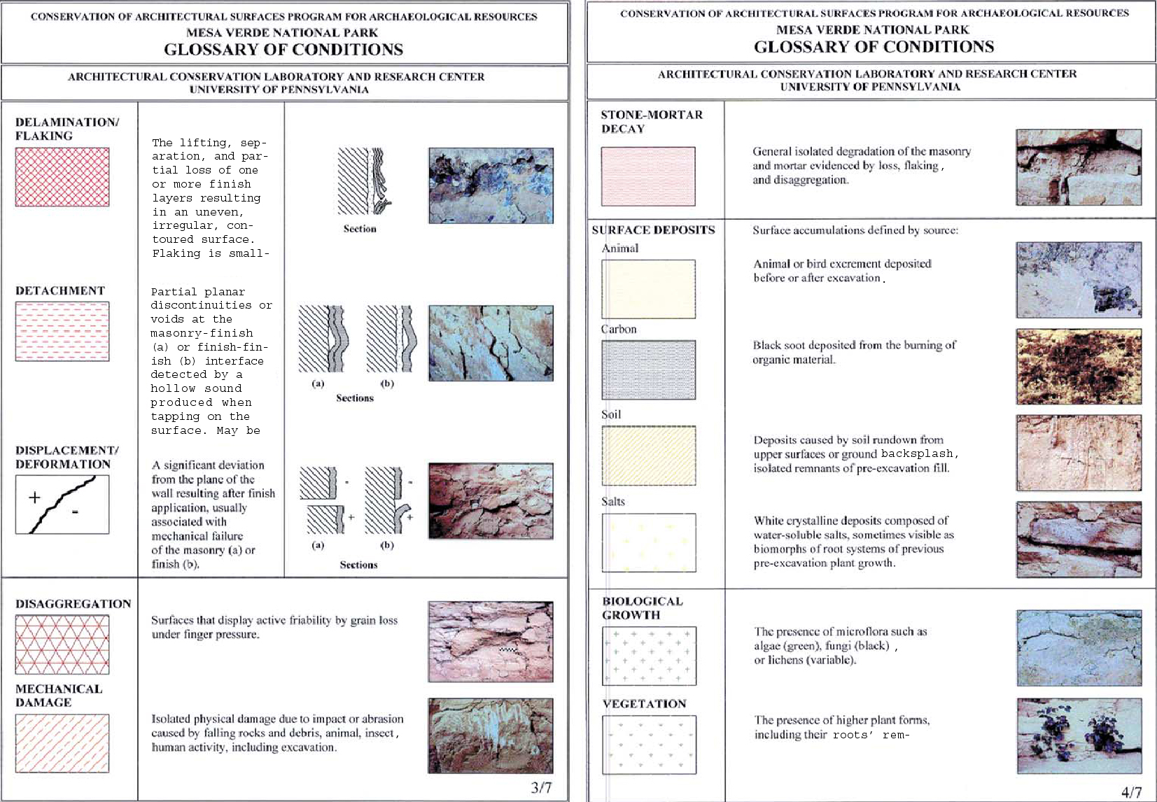
Most partial loss also occurs along this upper banquette wall face, often directly below areas of total loss, as well as along the base of the banquette (fig. 10, see page 61). Conversely the entire middle zone of the banquette walls retains the most complete finishes, especially on the pilasters. This pattern—although dependent on the specifics of room orientation, namely exposure and proximity of the space to the alcove's rear wall, surrounding wall height and configuration, and the number of superimposed finish layers—generally reveals the critical relationship among design, construction, and weatherability. The finishes on the walls directly under the flat banquette ledges between the pilasters succumb to the wind-driven rain and melting snow that accumulate on these flat, horizontal upper surfaces along the outer west and northwest sections. This pattern of precipitation has been observed in action and can be deduced from the succession of related conditions along the upper banquette wall, beginning at the top with total loss and detachment and deformation of the remaining plaster edges, to partial loss and delamination lower down the wall. The telltale evidence of new and old soil wash patterns in these locations down the upper and lower walls (monitored over two years) clearly points to active water flow channeling. This activity leads to the probable sequence of plaster decay including saturation, swelling, and shrinking of the clay fraction of the finishes, salt formation, deformation, blistering and detachment of the layers, debris accumulation in the detachment, and eventual mechanical failure and loss. These conditions have been recently induced in sequence through laboratory simulation in preparation for treatment testing and evaluation. Changes in partial loss over time clearly indicate the active nature of this condition in exposed areas (Carr 2002). Conversely, the lower eastern walls along the rear of the alcove display less differential damage relative to the banquette shelves and no soil wash, presumably due to the protection afforded by the extreme depth of the alcove (fig. 11, see page 62). However, what can be observed along the lower rear walls is severe delamination and flaking, salts, and intralayer root masses, the latter responsible for post-1960 loss of the last dado layer along the upper banquette wall. These conditions suggest typical moisture problems related to cyclical wetting from driving rain and snow and frequent thermal cycling. In fact, Kiva C is uniquely situated in the alcove so that its western half experiences prolonged wetting directly from rain and melting snow captured on the banquette tops, while its eastern half experiences some direct wetting from heavy precipitation events. In addition, sulfate and
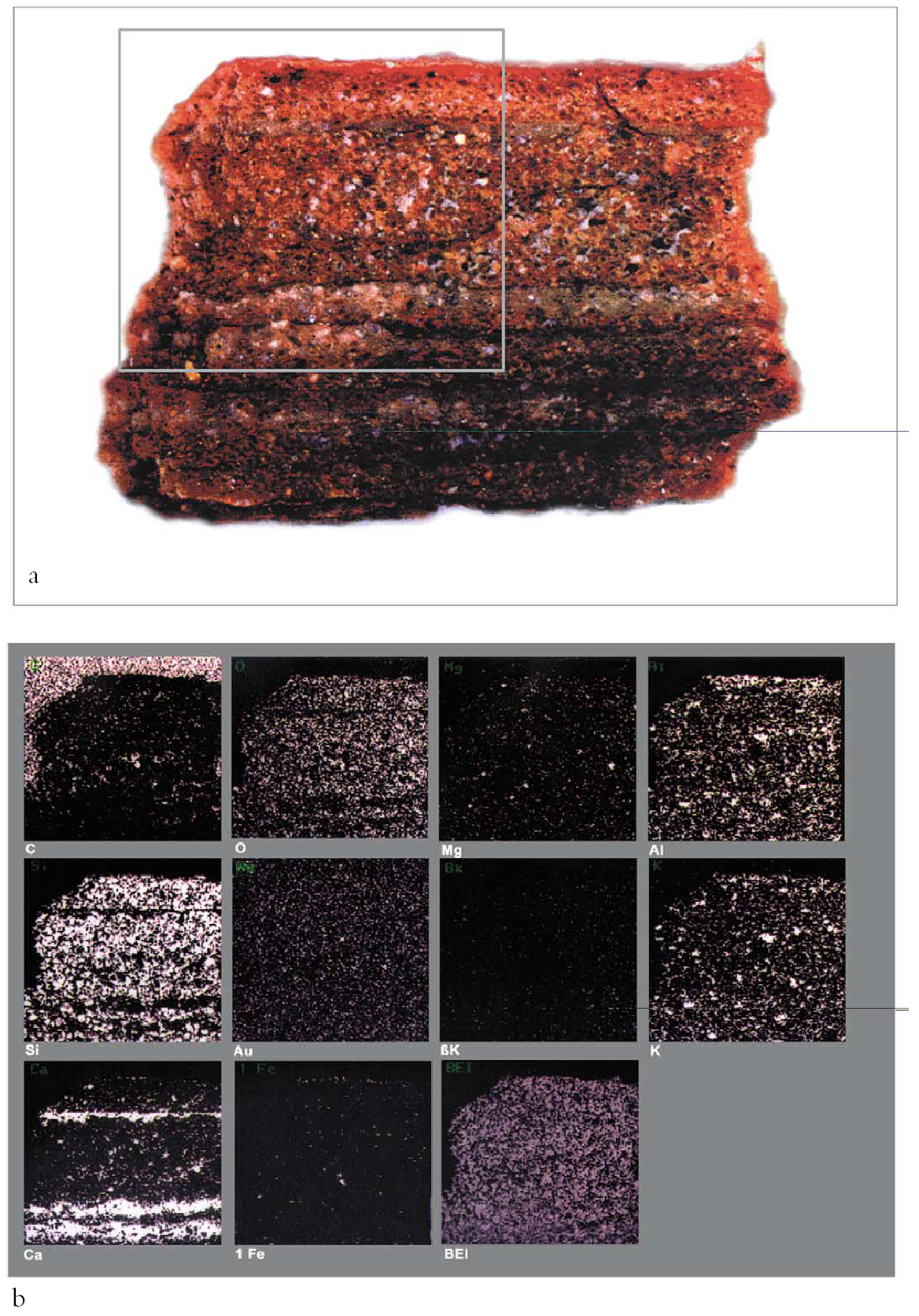
Overall patterns of groundwater emergence for the entire alcove are further complicated by the orientation of the north-south dip of the alcove's shaley layers, which affects the location and quantity of water emerging from the rock. For example, those kivas and rooms located along the rear of the northern half of Mug House, upslope of the shaley seam, exhibit far more salts, presumably due to the initial discharge of water at this end. Conversely, rooms along the rear of the southern half, downslope of the shaley seam, display less efflorescence and water damage where protected from wind-driven rain and snow. Based on this evidence, room location within the alcove—especially as it relates to rear wall moisture determined by the activity of water percolation and the orientation of the shale seam, subterranean ground elevation, as well as exposure to the weather—is critical in determining plaster conditions. No doubt the immediate physical context of each space, such as the surrounding wall heights, creates unique climatic environments for each architectural feature and associated surface finishes. Nevertheless, the specific combinations of conditions observed in Kiva C at Mug House reveal the importance of siting within the alcove and the complexity of primary and secondary factors in the explanation of basic decay mechanisms (see fig. 7, page 60). After environment, composition and layer structure of the finishes, in association with the deposition of carbon soot and embrittlement from intense burning, play an important role in determining condition. All surface finishes examined thus far reveal a well-proportioned ratio of kaolinite-illite clay binders to a fine but well-graded and sorted silt and quartzitic sand fraction, thus ensuring initial good adhesion and low shrinkage of these finishes (Dix 1996, 88–90) (table 1). Cryptocrystalline calcite found in the soil used to prepare the plasters and also possibly deposited subsequently from bicarbonate-rich groundwater helped to give good durability to these finishes. The possible presence of organic plant additives, as recorded in late-19th-century ethnographic accounts, could have also provided short-term durability,
Layer structure, and indirectly masonry construction, is without doubt a significant factor in finish condition. With very few exceptions, each plaster layer applied probably represents a single campaign, evidenced by heavy carbon soot buildup and separation fractures that often occur between layers over time. Of all the building and room types, kivas, without exception, contain the greatest number and most complex application of surface finish layers and intralayer soot deposits (fig. 12, see page 63). This condition may well be due to the largely ceremonial
Given the weak and brittle nature of these earthen finishes (when dry), layer stability is generally inversely proportional to the number of layers applied to the surface. As with other plastered masonry, the earthen finishes adhere best to the earthen mortar joints regardless of keying, and less well to the stone. Intralayer delamination often results from poor adhesion caused by carbon soot deposits at these interfaces. Once detached, salts and roots find ideal environments to develop further, thus exacerbating the problem of delamination, salt formation, and moisture retention. At Mug House, most kivas are carefully constructed with regular, well-shaped, and finished stones, especially for the pilasters and lower banquette wall. This construction has the effect of ensuring a smooth, curvilinear surface upon which to apply the numerous thin earthen plasters and washes needed to complete the architecture.4 Only Kiva C, whose masonry is roughly shaped, finished, and coursed, has a thick initial leveling plaster of several centimeters applied to the masonry substrate and followed by subsequent thin finish plasters and washes, some of which appear to have been burnished (lower red dado). As a result, this construction technique has caused unique detachment problems in Kiva C, given the vulnerability of the thick base plaster. 4.2 DELAMINATION AND FLAKINGA subset of partial loss characterized as active surface (flaking) and intralayer (delamination) failure has been found extensively along the lower banquette walls, especially in combination with salts and previous root growth. 4.3 DETACHMENTLoss of bond between the plasters and their masonry substrate occurs as either open or blind separation. This loss is found as a narrow linear zone across much of the upper top edge of the lower banquette wall. It is a discrete condition often occurring in conjunction with total or partial loss since excavation (recorded as “loss since Rohn”; see fig. 6, page 60) due to exposure and failure resulting from wet/dry deformation and stress cracking, debris accumulation pressure, and falling damp. 4.4 BLISTERINGThe wetting, swelling, delamination, and subsequent deformation of thin single or multiple layers of plasters and washes result in the formation of blisters of variable sizes and shapes. Often these exist in various stages as blind, cracked, and broken forms, always in locations where water has been or still is present. Although this condition is prevalent in other spaces, its occurrence at Kiva C is very limited. 4.5 CRACKINGNo major structural failure exists in Kiva C, although some cracking is related to previous joint and masonry movement that has been translated to the plasters. Map cracking occurs in isolated areas, particularly the lower rear wall in association with root mass–related delamination. There is no evidence to suggest that this map cracking was caused by initial shrinkage of original plasters. However, areas of repeat wetting and drying indicate stress failure in the form of map cracking. 4.6 MECHANICAL DAMAGEMechanical damage occurs in isolated areas, especially along the lower walls as random scratches that appear to be due to animal activity and as small divots from the inadvertent strike of the excavators' trowels into the plaster. This damage is not related to any other conditions. |