INVESTIGATION INTO THE DETERIORATION OF PAINTINGS AND PHOTOGRAPHS USING COMPUTERIZED MODELING OF STRESS DEVELOPMENT
MARION F. MECKLENBURG, MARK McCORMICK-GOODHART, & CHARLES S. TUMOSA
4 NUMERICAL SOLUTIONS: COMPUTER ANALYSES OF PAINTINGS AND PHOTOGRAPHS
Structural analyses were conducted using finite element analysis (FEA) and the digital computer. The program used in the computer modeling in this paper was ANSYS, version 4.4, run on a 33 MHz 386 desktop computer with 4 MB RAM.
4.1 MODELING THE EFFECTS OF DESICCATING AN ILFOCHROME PRINT
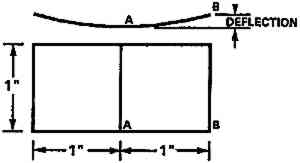
Low RH levels are currently recommended for long-term preservation of photographic materials because of an incremental improvement in chemical stability. For example, conditioning to 25–30% RH is recommended for color films prior to placing them in cold storage (Eastman Kodak Co. 1985). To study the physical stress and dimensional changes that can occur in a photographic material as a consequence of the recommendation, a section of an Ilfochrome photograph was modeled. Ilfochrome (formerly called Cibachrome) is manufactured by Ilford Photo Corporation and employs a unique silver dye bleach process. The finished print is mechanically typical of a wide range of photographic materials coated on a polyester film base (Sturge et al. 1989). The image dyes are dispersed in a gelatin binder layer, and on the reverse there is an anticurl layer, which is gelatin with incorporated glass particles acting as a matting agent. The glass increases the stiffness of the gelatin backing layer and also reduces the moisture coefficient of expansion. From a structural point of view, there are then at least three material layers with distinct mechanical properties. The image layer is 0.000652 in (0.00166 cm) thick, the polyester base is 0.007 in (0.0178 cm) thick, and the anticurl layer is 0.00049 in (0.00125 cm) thick. The primary measurement used to evaluate the accuracy of the computer model was curling (deflection at an edge) of the photograph as it dried out. If the balance of stresses in the various layers of the Ilfochrome specimens was calculated correctly, then the deflection of various sized specimens, with and without all layers in place, should be calculated properly by the model. Figure 7 shows the dimensions of a test specimen and the deflection at the corner that was actually measured on each specimen and also calculated. Two different size test specimens were used. The first was 1 in wide and 2 in long, and the second was � in wide and 2 in long. Both types of specimen were held flat to a plane surface along a center line perpendicular to the length while the edges were allowed to curl freely. The experimental deflections were measured at intervals between 60% RH and 15% RH.
Fig. 7.
Dimensions of the Ilfochrome experimental test specimen showing the displacement, both measured and computed.
 |
The polyester layer was modeled with the measured moisture coefficient of expansion of 0.0000077/1%RH and a modulus that varied as a function of RH:
Fig. .
 |
Initially, the function of Ee(RH) shown in eq 13 along with the constant moisture coefficient of expansion of 0.000044/1%RH for photographic gelatin was programmed into the computer. The role of the glass was assumed to be minor, allowing the anticurl layer to be modeled as if it were slightly stiffer and with lower coefficient of expansion similar to the properties reported for the rabbit skin glue. The results predicted for the complete Ilfochrome structure were reasonable but failed to predict accurately the behavior of an Ilfochrome specimen when the anticurl layer was removed.
To refine the model, a more detailed approach was taken. The more accurate nonlinear moisture coefficient of expansion determined in our laboratory was assumed for the Ilfochrome emulsion layer: α = 0.0008 - (0.0000087 � RH).
Next, the computer was used to assist in determination of an effective Ee(RH) for the emulsion layer of the print. This was accomplished by first chemically stripping the anticurl layer, cutting � � 1 in print specimens, and then measuring the deflections in different RH environments. The purpose of removing the backing layer was to simplify the model to a two-layer system. Since the mechanical properties of the polyester base layer were straightforward to measure directly (by removing all coating layers) this reduced the problem to one “unknown” layer and allowed the computer to “backsolve” for the properties of the Ilfochrome emulsion layer. Thus, by iteratively choosing Ee(RH) and “back solving” for the deflections of a � � 2 in experimental print sample using the computer, the effective modulus, Ee(RH), was calculated to be a nearly constant 190,000 psi. This result is in remarkable agreement with the properties of the photographic gelatins cast in our laboratory and measured under quasi-equilibrium restrained conditions, once the nonlinear moisture coefficient expansion was taken into consideration. As can be seen in figure 8, the results showed that the computer tended to average the effective modulus over the test environments examined. Note that the line labeled “Original Fit, Calculated,” is the effective modulus calculated using the mathematical fit from eq 13, which was developed using the constant moisture coefficient of expansion equal to 0.00044/1%RH. An important lesson in this experimental work was that fact that the computer can be an effective tool in helping to determine mechanical properties needed for analyses. In this case, it allowed us to gain confidence that the manufactured gelatin emulsion with incorporated image dyes and perhaps other proprietary chemical additives was not fundamentally different from gelatin cold-dried films hand cast in our laboratory in terms of its mechanical properties. Further, once the effective modulus for the emulsion layer was determined, the material properties for the anticurl layer could then be derived in a similar test manner. The anticurl layer was determined to function essentially as a constant at Ee(RH) = 360,000 psi. Finally, if all calculations bear truth to the complete Ilfochrome structure, different geometries and configurations should be predicted accurately. Figure 9 shows the Ilfochrome deflection results, both calculated and measured, of the � in wide specimen. Also shown in that figure is the computer solution and experimental results for a 1 in wide specimen. The bracket boxes indicate that the 1 in wide specimen without anticurl layer was twisting at the corners where the computer model did not. This behavior is most likely due to the fact the polyester material properties exhibited some subtle anisotropic behavior in the length and widthwise directions that was not measured in the polyester tests. Nevertheless, the computer model accurately predicted that a change in geometry from � in to 1 in width would result in a significantly greater amount of curl. This result is clearly not intuitive, since it might easily be reasoned that the wider base would have a cross-bracing effect and cause less deflection to occur in the lengthwise direction of the object. Figure 10 shows the calculated results of complete 1 � 2 in Ilfochrome sample with all layers in place compared to the actual deflections measured in the complete Ilfochrome specimen. There is little difference in the two sets of data. Also on this plot is the computer simulation of the film as if the glass particles were removed from the anticurl layer. The anticurl layer would then possess material properties of the gelatin only. This demonstrates the remarkable stiffening effect of the glass. In figure 11, the computed stresses for the emulsion and anticurl layers are presented for the complete 1 in wide model. These are very high, and it is not unreasonable to expect that they will lead to edge delamination and emulsion cracking of the prints. From a conservation point of view, the stresses induced by cycling from commonly encountered environments to the present recommend dations of 25–30% RH are undesirable. In the presence of defects such as cracks or at edges, the high stresses represent the source of delamination of the layers.
Fig. 8.
Effective modulus versus percent relative humidity for different photographic gelatin. The plot shows the effect of improving the mathematical expression of the moisture coefficient of expansion and the back-solved solution.
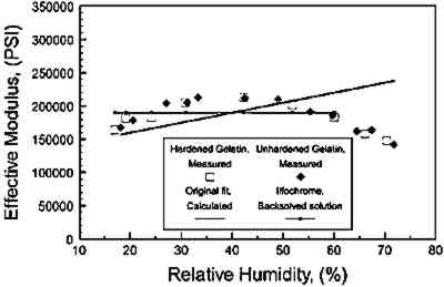 |
Fig. 9.
Computed and measured deflections of the Ilfochrome samples stripped of the anticurl layer. Also shown is the back-solved solution of the � in wide sample used to verify the measured effective modulus of the gelatin.
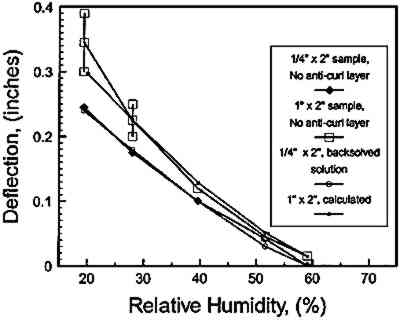 |
Fig. 10.
Computed and measured deflections of the Ilfochrome samples having all layers. Also shown is the solution of the 1 in wide sample with the glass removed from the anticurl layer.
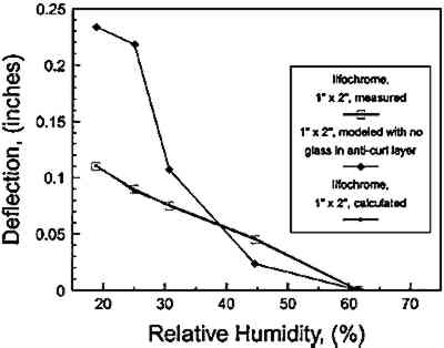 |
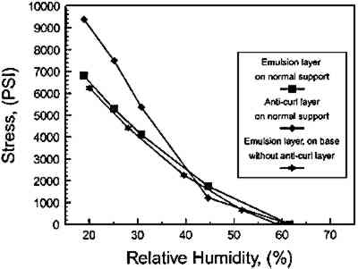
Fig. 11.
Calculated stresses in the image and anticurl layers of the Ilfochrome computer model resulting from desiccation from 62% to 18% RH.
 |
4.2 MODELING THE EFFECTS OF COOLING AN ILFOCHROME PRINT
The effects of cooling the same print results in entirely different stresses. The thermal coefficient of expansion for the photographic gelatin is γ = .000030/�C and for the polyester base, γ = (.00000616 + .00000043 � T)/�C. The effective modulus for the photographic gelatin at 50% RH was determined to be
Fig. .
 |
and the effective modulus for the polyester base was
Fig. .
 |
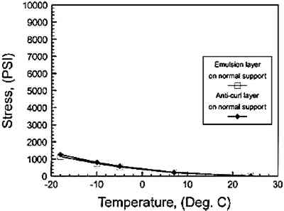
Figure 12 shows the computed stresses in the emulsion and anticurl layers of the Ilfochrome when cooled while maintaining a constant moisture content established by 50% RH. The calculated levels are substantially lower than the stresses developed by desiccation while holding temperature constant at 22�C. Since cooling also increases the chemical stability, the numerical analysis of Ilfochrome supports the premise that long-term storage recommendations for photographic materials should weigh the merits of cooler temperatures at moderate relative humidity more highly than the use of sharply reduced relative humidity levels to achieve overall improvements in the life of photographic materials.
Fig. 12.
Calculated stresses in the image and anticurl layers of the Ilfochrome computer model resulting from cooling from 22�C to −18�C.
 |
4.3 MODELING THE EFFECTS OF DESICCATING A PAINTING
A 30 � 40 in (76 � 102 cm) painting was modeled and subjected to changes in relative humidity while the ambient temperature was held at 23�C. The layer of the painting consisted of a linen 0.025 in (0.064 cm) thick, modeled as a 0.006 in (0.0152 cm) layer; a glue layer 0.004 in (0.00508 cm) thick; and a Naples yellow oil paint layer 0.003 in (0.0076 cm) thick. Test results showed that a stretched fabric developed minimal stress with desiccation. This was the result of a severely decreasing modulus with desiccation (Mecklenburg 1982). The stretcher was not expanded. Each of the layers of the model painting were programmed with their respective material properties taken from the data presented earlier in this paper. In order to obtain greater analytical detail, it was possible to take advantage of the painting's double symmetry and model only the upper right quadrant. This modeling was done by programming the appropriate material properties equations for each of the individual layers of the model painting as well as the proper boundary conditions. In this case, the paint layer was Naples yellow. For the changes in RH, E(RH) = 51,800 - 840xRH was the equation used. For the strain calculations, a moisture coefficient of 0.0000257/1%RH was used. For the glue layer, the modulus was obtained as discussed previously under RH, and the strains were calculated using a moisture coefficient of 0.000264/1%RH. The fabric was assumed to be a minimally contributing material, since glue sizing a stretched linen removes any residual stress in the fabric. In this case, the modulus was assigned a nominal constant 5 ksi (35 MPa) and the moisture coefficient was an average 0.0001/1%RH.
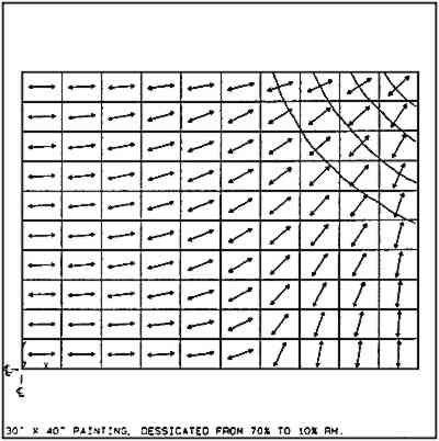
The model painting was desiccated from 70% to 10% RH at 23�C. The results of the analysis showed the stresses in the paint layer ranging from 0.1 ksi (.698 MPa) to 0.28 ksi (1.93 MPa). The distribution of the stresses are shown in figure 13. This distribution is not uniform, and high stresses occur in the corners. Cracking, if it occurs, will initiate mainly in the corner regions of the painting, as shown in the quarter-view in figure 14. In this figure, both the direction vectors of the principal stresses and the possible crack pattern are shown. If the equilibrium breaking strength of the paint at 5% RH and 23�C was low, only 0.2 ksi (1.38 MPa), the cracks would run no farther than about 3 in (7.6 cm) from the corner.
Fig. 13.
Computer calculated, maximum principal stress contours for a 30 � 40 in traditional canvas-supported oil painting subjected to desiccation from 70% to 10% relative humidity at 23�C.
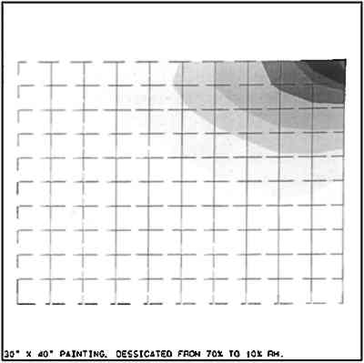 |
Fig. 14.
Principal stress directions and the projected crack pattern of a 30 � 40 in oil painting subjected to desiccation from 70% to 10% RH at 23�C.
 |
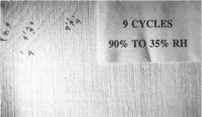
To check these results experimentally, a painting was constructed by stretching a medium-weight, basketweave linen fabric onto a 20 � 30 in (50 � 75 cm) stretcher. A rabbit skin glue size was applied warm. After the size was thoroughly dry, a gesso mixture was applied. This gesso had the mechanical properties of a brittle paint. The mixture had a pigment-volume concentration of 93 (Mecklenburg 1991), a strength of approximately 180 psi (1.24 MPa) and a rapid loading modulus of approximate 600,000 at 50% RH and 23�C. The moisture coefficient was less than 0.0001/1%RH. This coating is stiffer and weaker than one would expect from an old oil paint. The experimental painting was subjected to 9 cycles of changing RH. The cycles were extremely severe, starting at 50% RH, going to 90% RH, to 35% RH, and back to 50% RH. This range was selected to produce the maximum possible damage. The painting was inspected after each cycle. The results of the experiment are shown in figure 15, where cracks are appearing in the corners of the “painting.” These cracks are as the computer predicted and extend no further than about 3 in (7.5 cm) from the corner of the painting. The numbers in this illustration show the crack-tip location at the end of the noted RH cycle. There were no cracks in areas other than the corners. The result of the computer model and the experiment suggest that the model is reasonably accurate but somewhat conservative—that is, it predicts more severe cracking than would actually occur. Similar studies have been done by others (Karpowicz 1989, 1990) with similar results.
Fig. 15.
Photograph of the corner of an experimental 20 � 30 in painting subjected to severe humidity cycling. The cycling resulted in the cracks forming as predicted by the computer model.
 |
4.4 MODELING THE EFFECTS OF COOLING A PAINTING
The same 30 � 40 in (76 � 102 cm) painting was modeled and subjected to changes in temperature while the ambient RH was held at 5%. The glue layer was characterized using a thermal coefficient of 0.000025 per �C and a changing modulus that varied linearly from 705 ksi (4,860 MPa) at −3�C to 550 ksi (3,791 MPa) at 23�C. The data were used to develop the equation
Fig. .
 |
where T is the temperature in �C. The fabric was programmed with an average constant modulus of 5 ksi (38.6 MPa) and a thermal coefficient of 0.00001 per �C. The distribution of the principal stresses in the paint layer, calculated by the computer, is shown in figure 16. This stress distribution is quite uniform, ranging from 0.303 ksi to 0.307 ksi (2.09 MPa to 2.11 MPa), and just reaches the measured breaking strength of Naples yellow paint at 5% RH and −2�C. This finding suggests that cracking of the paint layer will occur throughout the surface of the model painting when the temperature is decreased from 23�C to −3�C at 5% RH. It most certainly would occur if the starting environment were 23�C and 50% RH. This cracking would be the consequence of the combined adverse effects of both desiccation and cooling.
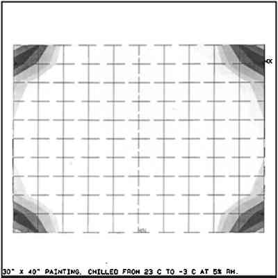
Fig. 16.
Computer-calculated, maximum principal stress contours for a 30 � 40 in traditional canvas-supported oil painting subjected to cooling from 23�C to −3�C at low RH.
 |
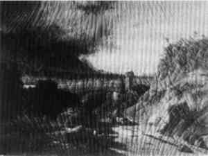
The stresses have a directional bias as shown in figure 17. The principal stresses are indicated by the calculated directional vectors (arrows), and cracking that occurs will do so perpendicular to the vectors as shown by the continuous lines. This crack pattern shows up frequently in paintings in North America, as shown in figure 18, a 19th-century landscape painting measuring 20 � 28 in. The glue layer principal stresses reached levels ranging from 4.72 MPa to 5.13 MPa (.685 ksi to .745 ksi).
Fig. 17.
Principal stress directions and the projected crack pattern of a 30 � 40 in oil painting subjected to cooling from 23�C to −3�C at low RH.
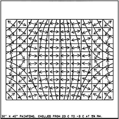 |
Fig. 18.
Photograph of a 19th-century painting showing the crack patterns similar to those generated by the computer model painting subjected to cooling. This pattern is fairly typical of a large number of paintings found in North America.
 |
|