THE DEVELOPMENT OF THE HUMIDITY CONTROL MODULE AT FIELD MUSEUMCATHERINE SEASE
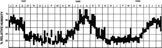
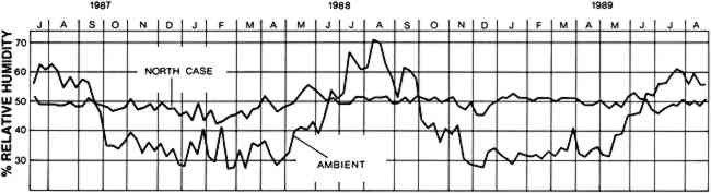
ABSTRACT—Field Museum of Natural History, Chicago, has implemented the use of relative humidity modules to control relative humidity in display cases containing moisture-sensitive objects. The humidity control module developed at the Canadian Conservation Institute has been used to control two cases since 1987. Problems encountered with its performance over 10 months led to modifications of the module. Three more modules were installed in 1988 in a larger, more complicated exhibit. This paper outlines the development and modification of the modules and their performance over four years. 1 INTRODUCTIONCONTROLLING RELATIVE HUMIDITY in exhibit halls at Field Museum of Natural History, Chicago, is difficult. The present building opened in 1921. Like other large museums of this period, Field Museum contains an expansive central hall of approximately one million cubic feet stretching the entire length and height of the building. Large exhibition halls open off this main hall on two levels. All of these public areas are interconnected; only 2 of the 34 exhibit halls are discrete spaces. Over the past decade, various climate control systems have been installed in different parts of the museum. While they have made the building much more comfortable for staff and visitors, they have had minimal effect on the well-being of the collections on display. The existing climate control systems cannot effectively control the exhibit areas of the museum to the exacting standards required for the protection of moisture-sensitive objects. For example, in the Webber Resource Center, a study hall on the first floor of the museum, the yearly fluctuation of relative humidity ranges between 23% and 77% (fig. 1). The weekly fluctuation is minimally 4% and has been as great as 25%. Relative humidity levels in other halls, while not exactly the same as in the Webber Resource Center, show similar weekly and yearly fluctuations. Such fluctuations in relative humidity have contributed to the warping, cracking, and splitting of many artifacts on display throughout the museum.
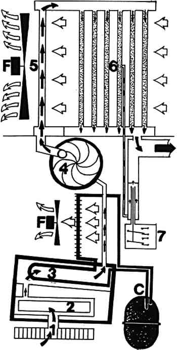
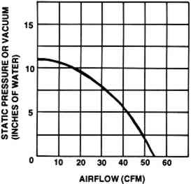
In 1986, Field Museum embarked on a major renovation of its exhibition areas. The majority of these projects involve the Department of Anthropology's collections of ethnographic and archaeological materials, a large proportion of which are composed of moisture-sensitive materials, including leather, skin, wood, bone, ivory, and fibers of all kinds. These projects involve moving artifacts from the stable environment of climate-controlled storerooms to a fluctuating environment in exhibit halls. 2 THE HUMIDITY MODULETHE DELETERIOUS effects of the lack of relative humidity control on museum objects has long been recognized (Macintyre et al. 1934). Considerable effort has been made by scientists, engineers, conservators, and other museum personnel to control the relative humidity in exhibit areas. Today, new museums are constructed with heating, ventilation, and air-conditioning (HVAC) systems capable of controlling the relative humidity to the strict standards set by preservation needs. While older structures can have new HVAC systems installed (Briggs 1980), they appear to be less effective than those in new structures, as the buildings were not originally designed to meet these environmental standards. Since large HVAC systems are costly to install and maintain, other alternatives to humidity control have been sought. Most of The prototype of Field Museum's humidity module was designed by Stefan Michalski of the Environment and Deterioration Research Division of the Canadian Conservation Institute (CCI) in Ottawa (Michalski 1982). Instead of trying to condition the museum as a whole or exhibit halls as discrete spaces, this module provides humidity control of only those cases containing moisture-sensitive objects. The module is a small, compact, and simple machine that provides low-cost, low-maintenance control of relative humidity in enclosed spaces (fig. 2). It is a small-scale mechanical control system, featuring a blower, a heat exchanger to keep the conditioned air at room temperature, and a silica gel column to smooth out the humidity output of the humidifier and dehumidifier. Each module measures 20.5 � 22 � 59.5 in and requires a standard electrical outlet, a plumbed-in source of water, and a drain.
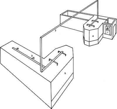
The module is easily connected to each case with a system of plastic tubing. A 2-in diameter main supply tube extends from the module, with 1/2–1 in diameter supply tubes branching off it to enter each case. These smaller tubes are sized individually for each case to control the airflow to that case. Exhaust is provided simply by natural leakage through seams in the case. A single module can be used to control more than one display case. The total volume and the seal of the cases are the deciding factors in determining the number of cases a single module can control. Michalski (1985) calculated that one module can control approximately 2,700 cu ft of air if the cases are reasonably well sealed. This figure was later revised by Michalski (1987) to 3,500 cu ft. Since connecting a case is simply a matter of drilling a small hole and inserting the plastic tubing, installation is not a major job involving significant costs. As a result, the module allows for extreme flexibility in designing and changing exhibition areas. If the contents of a case are changed and no longer require humidity control, the tubing can be pulled out. As existing display cases The module will produce and maintain a level of relative humidity within a range of 40–60% with variation around a given relative humidity set point of no more than � 3% (Michalski 1985). The humidity output of the module is dependent on the uniformity of the temperature throughout the room in which the cases are placed. The module does not control the temperature of the conditioned air but rather actively follows the temperature of the room. Therefore, if the temperature inside a case is warmer or cooler than the air surrounding the module, the relative humidity inside that case will be lower or higher, respectively, than the output of the module. As long as there are no major temperature differences between the inside and outside of the case, the system should work well. One advantage of the module is that, unlike most mechanical systems, it is slow to produce extremely high or low relative humidity levels even if it malfunctions. Should the module fail to produce humidity, overhumidify, or stop altogether, the humidity levels in the case will not rise or fall drastically within the space of hours. The silica gel buffer column provides a slow response to a sustained change in the humidity. Instead of rising or falling immediately, the relative humidity in the case will gradually move toward the ambient relative humidity over a period of 9 or 10 days. In well-sealed cases, the column acts as a built-in safeguard against malfunction of the module. The advantages of the module are that it is mechanically simple, extremely flexible, able to control large volumes of display cases, relatively inexpensive ($8,750 at the time of writing), and easy to maintain. It appears to be ideal for museums that cannot consider strict climate control of the entire building yet have too many cases to make a buffer system too costly and labor intensive. 3 THE FIELD MUSEUM MODULEIN 1987, a local Chicago company, Kennedy-Trimnell, built the first module for Field Museum from blueprints provided by the Canadian Conservation Institute. Kennedy-Trimnell now produces the modules commercially. In July 1987, the first module was installed in the Webber Resource Center, a study hall containing Native American ethnographic material. Nearly all of the artifacts on display are composed of moisture-sensitive materials, The module was connected to two large walk-in cases with a combined volume of approximately 3,000 cu ft. A system of plastic tubing was used to connect the module to the cases. Two-inch diameter polyethylene tubing formed the main supply feed from the module to the tops of the cases. The cases face each other, one on the north side of the hall and the other on the south, so it was necessary to suspend a 30-ft length of this tubing from the ceiling to connect the two cases (fig. 3). A 2-in diameter supply tube was installed along the length of the top of each case, with 1/2-in diameter tubes branching off perpendicularly. These smaller tubes were connected to 1/2-in diameter holes perforating the ceiling of each case for the entry of the conditioned air. Once the module was installed, these holes were fitted with plastic plugs with openings of 1/8–1/2 in diameter to regulate the airflow through the cases. A thermal anemometer was used to measure the airflow from each hole. Where the airflow needed to be decreased, a plug with a small hole was used. Where the airflow needed to be increased, a plug with a larger hole was used. In this way, the airflow throughout the system was equalized.
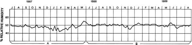
The module was set to maintain the humidity level in the cases at 50%. Recording hygrothermographs were placed in each case as well as in the hall itself to record the ambient relative humidity. The results for the north case, from June 1987 through June 1988, can be seen in figure 4.
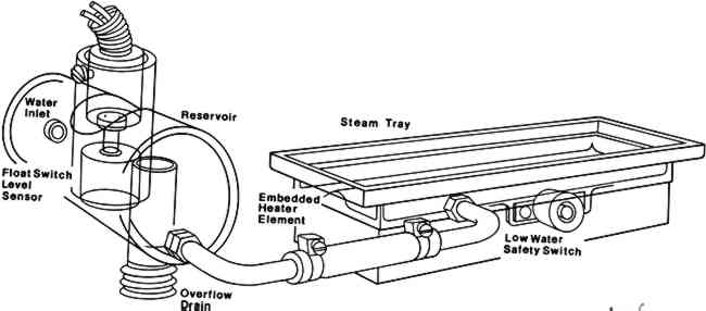
It took the better part of a week for the silica gel column in the module to adjust to its new environment and then to bring the relative humidity in the two cases to the desired level of 50%. Last-minute adjustments to the installation requiring staff access to the cases also affected the fluctuation of relative humidity during this first week. In subsequent weeks in July, August, and September, however, the machine did well. Through the end of August the relative humidity was maintained to within 2% of the set 50%, within 2.5% until the beginning of October. The module did not do as well in the subsequent winter months of 1987–88. During this period the ambient relative humidity in the hall averaged 32%, with a low of 23%. Nineteen weeks out of the 27 weeks, it dipped below 30%. The module was now in a humidification cycle that was not as effective as the dehumidification mode at maintaining 50% RH in the two cases. Although we were concerned about the relative humidity levels in these cases, the use of the module was regarded as a field test. Up to this point, adjustments and minor changes were being made to the module in response to the conditions in the exhibit hall and the behavior of the module. A recurring problem, for example, involved the water supply. Particulate matter in the water sporadically blocked the water line to the module, causing the reservoir and the humidifier's evaporative plates to dry up. During the summer months, when the module was dehumidifying and, therefore, not requiring water, this condition was not a problem. In the winter, however, the module, in its humidification phase, was constantly calling for water, and blockages in the water line prevented the module from maintaining a constant humidity level. To resolve this problem, various particulate filters were connected to the water line over a period of months. Although they improved the situation, they did not solve the problem altogether. The final solution was to increase the size of the tubing on the water line to 1/4 in diameter. Another problem involved the float valve that regulated the filling of the reservoir for the humidifier's evaporative plates. The valve was a mechanical switch attached to a long arm with a float on the end. This assembly was located inside a box that filled with water. As the water level rose, the float moved the end of the arm up shutting the mechanical valve that, in turn, shut off the water flow. The bottom of the box housing the float valve was open on one side to allow water to enter an adjacent box freely. This box contained eight evaporative plates that wicked up the water. When in a humidification cycle, the machine diverted the airflow through the box containing the evaporative plates to pick up moisture. The design of this whole assembly was mechanically cumbersome. The box in which the valve was located was too small and did not allow for a long enough level angle for the valve to work efficiently. As a result, the float valve was not sensitive enough to properly regulate the water supply, and constant readjustments were necessary to keep it working properly. In addition, the water pressure proved too strong for the valve, and it would not shut off the water supply. A pressure reducer was necessary to make the float valve work, but this device created additional problems. Once it exploded, causing a minor flood in the hall. In addition, the entire assembly leaked throughout this whole period. During the winter months, the solenoid, the switch that allowed the reservoir to maintain As the winter progressed, it became clear that the design of the module's humidification system did not enable it to provide enough humidity to maintain a level of 50% RH. To solve this problem, design modifications were made to increase the module's efficiency. As mentioned above, the float valve and evaporative plate system had proved awkward. Equally cumbersome was the way in which the airflow was switched to bypass the evaporative plates when the module was operating in a dehumidification mode. The arrangement made the module more complicated than need be, presenting more opportunities for mechanical failure. The module was simplified by replacing the evaporative plates with a steam generator, located in the cold box, as a means of humidifying the air. As well as providing more humidity, the steam generator system allowed the centrifugal blower to operate closer to its full potential, increasing the possible treated case volume from 3500 to 5500 cu ft. With the steam generator in the same box as the condensate coils, it was no longer necessary to switch the airflow back and forth. The steam generator consists of an electric resistance element embedded in a shallow die-cast tray located in the air intake (fig. 5). The tray is filled with water that is gravity fed from the auxiliary reservoir. The water level in the auxiliary reservoir is controlled by an electric valve consisting of a float valve and a solenoid. Water boiled in the tray provides the humidity needed for the system. The steam generator currently being used has a life of approximately 18 months and a replacement cost of $35 at the time of writing.
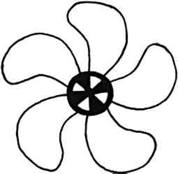
After the steam generator was installed in the last week of May 1988, fluctuations in the RH in the cases decreased to 4% (fig. 4). With the exception of a few periods, fluctuations have remained at this level. The drops in relative humidity, recorded in November and December 1988 and March 1989, occurred when safety switches in the module turned it off, when the fan motor and the solenoid burned out and when the steam generator tray needed cleaning. These problems led to further modifications of the module, the most significant of which was making the fan self-cooling. The fan blade assembly
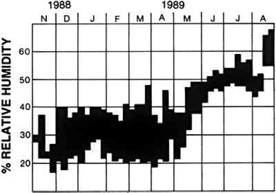
There was one instance of overhumidification, when the module failed to stop humidifying the air when it reached the 50% level. The plastic tubing connecting the humidistat with the center of the silica gel column had become kinked, and the relative humidity in the cases gradually reached 62% over a three-week period. At the time, the module was being monitored at monthly intervals. When the problem was discovered, the tubing was replaced with a thicker walled tubing while maintaining the original 1/8-in opening. The problem has not recurred. Maintenance of the modified module has been minimal. Once the steam generator was in use, the only chronic problem was with the water source, which will be discussed below. 4 EGYPTIAN EXHIBITTHREE HUMIDITY modules were used in the renovation of the Inside Ancient Egypt exhibit, which opened in November 1988. This was a much more ambitious use of these modules, as 55 cases were involved, ranging from large walk-in cases to small spaces less than 1 cu ft in volume. As these cases were spread out over 15,000 sq ft, an elaborate system of piping was needed to connect the cases to the modules. For example, polyethylene tubing was suspended from the ceiling in lengths of up to 80 ft to feed groups of cases. Conditions in this exhibit area differ from those in the Webber Resource Center discussed above. The exhibit is on the ground floor in an area where there is poor ventilation. From November 1988 through August 1989, the ambient relative humidity ranged from 17% to 70%. The average weekly fluctuation was 15.5%, while in one week the fluctuation was actually 27% (fig. 7).
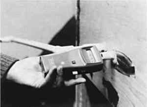
The machines in this exhibit were set to maintain the relative humidity in the cases at 42%. While a lower level might normally have been chosen for Egyptian material, the level of 42% was chosen to safeguard these particular objects. Unlike the objects in Webber Resource Center, these objects were not used to a stable environment. Inside Ancient Egypt was a renovation of an exhibit put together at least 40 years ago; much of the material, in fact, had been on display since the founding of the museum in 1893. Although no records exist, there is no reason to assume that the fluctuations in the relative humidity during those years was any different from those recorded in 1988–89 mentioned above. The objects had become stable with their environment in spite of these fluctuations. The level of 42% was chosen as the midpoint between the upper and lower levels of fluctuation and the level that would cause the least harm to the objects. The relative humidity level in the cases in this exhibit were monitored using a combination of recording hygrothermographs and a Rotronic Hygroskop GT humidity and temperature probe. In the large walk-in cases, weekly recording hygrothermographs were used to provide a continuous written record of the relative humidity levels. Initially, all cases were monitored to make sure the system of piping was working and that the desired relative humidity level was reached in each exhibit case. Then, as a string of cases was attached to each machine, a case toward the end of the string was chosen for continuous monitoring. We found this system provided an accurate and cost- and labor-effective way of Many of the cases in the exhibit were either too small to accommodate recording hygrothermographs (e.g., the animal mummy niches), or the presence of hygrothermographs would have greatly disrupted the aesthetics of the case (e.g. the simulated catacombs). In these cases, relative humidity was monitored using the Rotronic probe, which required special case construction. Three-quarter inch diameter polyethylene tubes were incorporated into the construction of each case. Inside the case, the open end of the tube was positioned so that it was not visible to someone viewing the case. The other end extended out the back wall of the case into a service area and was stoppered with a plastic plug. These cases were monitored by removing the plug, inserting the probe, and recording the probe's relative humidity digital readout (fig. 8). Initially, all cases were monitored once a day at the same time, every weekday, for several weeks to ensure the system was operating properly. Thereafter, periodic readings have been taken of randomly selected cases.
Initially, these modules in the Egyptian exhibit did not perform as well as the first one in the Webber Resource Center. In fact, throughout the winter of 1988–89, it was difficult to get them to produce any humidified air at all. The reason had nothing to do with the performance of the modules themselves, but rather with the water supply. Chicago's water is hard (135–40 ppm calcium). As water evaporated in the steam generator trays to produce humidity for the system, a thick encrustation quickly built up on the trays. This encrustation forced the heating elements to work harder. When they overheated, a safety switch turned them off. At first, attempts were made to remedy this situation by cleaning the steamer trays as needed with Lime-A-Way, a proprietary bathroom cleaner containing a mixture of dilute acids. Cleaning turned out to be a time-consuming and messy job, as each tray required cleaning at least once a week. The only viable solution was to connect a deionizer to the water supply of each module. During a humidification cycle, the module required 2 1/2 gal of water per day. No source of distilled water existed within reach of the modules to provide a plumbed-in source of pure water. Using a non-plumbed-in source of water would have involved modification of the module to provide a reservoir to hold the water and considerable daily maintenance to ensure the reservoir was kept full. A deionizer connected to each module allowed the local water supply to be plumbed in, keeping maintenance to a minimum. When one of the modules was tested with a deionizer, it worked extremely well, maintaining the relative humidity in its cases at the desired level of 42 � 2%. The steam generator tray required no cleaning at all. In June 1989, deionizers were connected to all three modules in the Egyptian exhibit. They are now working quite satisfactorily, producing the desired relative humidity level of 42 � 2% in the cases. 5 CONCLUSIONSTHE MODULE in the Webber Resource Center has been in operation now for more than four years. Since the switch to the steam evaporator system in May 1988, the relative humidity in its two cases has been consistently maintained at 50 � 2%, excluding the periods with mechanical problems mentioned above. Including these periods, the module has maintained an average of 48% RH. Although
While the above description may suggest that a break-in period is necessary, the modifications to the module described in this paper have eliminated the necessity for such a period. In August 1989 and September 1990, five modified modules were installed in Field Museum's new Pacific exhibit. These modules have maintained the relative humidity in the cases at the set 50% level from the time they were installed. Nevertheless, for the first time user, a break-in period is recommended. It is also clear that if the water supply is hard, it will be necessary to use deionizers with the humidity modules. In summary, we are very pleased with the performance to date of the humidity module. The staff of the Division of Conservation believes it has found a workable solution to the problem of displaying moisture-sensitive materials in uncontrolled exhibition areas and is making a long-term commitment to the use of more modules. ACKNOWLEDGEMENTSTHIS PROJECT was funded in part by the National Endowment for the Arts (grant 88-4432-0248). I thank Ralph and Sally Trimnell for their help throughout this project, for the drawings in figures 2 and 5, and for technical information in preparing this paper. Thanks also to Stefan Michalski, Richard Pearson, and Daniel Weinstock, without whom this project would not have been possible. Based on a paper in the Objects Update Session at the AIC 17th Annual Meeting, June 1989. 6 MODULE SPECIFICATIONS
REFERENCESBriggs, J.1980. Environmental control for old buildings: Two case studies. In Conservation within Historic Buildings, ed.N. S.Brommelle et al. London: International Institute for Conservation. 9–14. Kenjo, T.1982. A rapid-response humidity buffer composed of nikka pellets and Japanese tissue. Studies in Conservation27:19–24. Lafontaine, R. and S.Michalski. 1984. The control of relative humidity: Recent developments. ICOM Committee for Conservation Preprints, 7th Triennial Meeting, Copenhagen, 2:84.17.33–37. Macintyre, J., S.Stillwell, R.Knight, R.Wilsdon, W.Constable, and S.Cursiter. 1934. Some notes on atmospheric humidity in relation to works of art. London: Courtauld Institute of Art. Michalski, S.1982. A control module for relative humidity in display cases. In Science and technology in the service of conservation, ed.N. S.Brommelle and G.Thomson. London: International Institute for Conservation of Historic and Artistic Works. 28–31. Michalski, S.1985. A relative humidity control module. Museum146,37(2):85–88. Michalski, S.1987. Personal communication. Noonan, C.1975. Solving a humidity control problem. Canadian Museums Association Gazette8(2):21–25. Organ, R.1957. The safe storage of unstable glass. Museums Journal56(11):265–72. Padfield, T.1966. The control of relative humidity and air pollution in show-cases and picture frames. Studies in Conservation11:8–30. Padfield, T.1978. In search of the black box: A report on the proceedings of a workshop on microclimates. Toronto: Royal Ontario Museum. Sack, S.1963–64. A case study of humidity control. Brooklyn Museum Annual. 99–103. Stolow, N.1966. Fundamental case design for humidity sensitive collections. Museum News44(11):42–52. Stolow, N.1977. The microclimate: A localized solution. Museum News56(2):52–63. Thomson, G.1964. Relative humidity-variation with temperature in a case containing wood. Studies in Conservation9:153–68. Thomson, G.1977. Stabilization of RH in exhibition cases: Hygrometric half-time. Studies in Conservation22:85–102. Toichi, K.1959. Humidity control in a closed package. Studies in Conservation4:81–87. Weintraub, S.1982. A new silica gel and recommendations. AIC preprints, 10th Annual Meeting, American Institute for Conservation, Washington, D.C.169–73. SOURCES OF MATERIALS USEDHumidity Control ModuleKennedy-Trimnell, Inc., 109 N. Kenilworth St., Oak Park, Ill. 60301, (The company provides installation as well as the modules themselves and can supply more detailed specifications of the module.) Rotronic Hygroskop GT, (two-wire humidity transmitter)Rotronic, Badenerstrasse 435, CH-8040, Zurich, Switzerland, Distributed by: Thermo/Cense, 942 Turret Court, Mundelein, Ill. 60060 Lime-A-WayBenckiser Consumer Products, Greenwich, CT 06830, Distributed by:, local supermarkets and hardware stores nationwide AUTHOR INFORMATIONCATHERINE SEASE is head of the Division of Conservation at Field Museum of Natural History, Chicago. She has an A.B. from Bryn Mawr College and a B.Sc. in conservation from the Institute of Archaeology, University of London. She taught in the Conservation Department at the Institute of Archaeology prior to joining the staff of the Objects Conservation Department at the Metropolitan Museum of Art in 1979, where she was the head conservator for the installation of the Rockefeller Wing of Primitive Art. She worked privately in New York before joining the staff of the Anthropology Department at Field Museum in 1986. She has worked on numerous excavations in Britain, Greece, and the Middle East. Address: Field Museum of Natural History, Roosevelt Road at Lake Shore Dive, Chicago, Ill. 60605.
 Section Index Section Index |