DIGITAL RADIOGRAPHY IN THE ANALYSIS OF PAINTINGS: A NEW AND PROMISING TECHNIQUEA. Everette James, S. Julian Gibbs, Malcolm Sloan, Ronald R. Price, & Jon J. Erickson
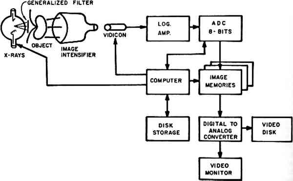
ABSTRACT—Recent advances in computer processing of images and the development of electronic x-ray detectors have made possible the development of digital radiographic techniques, which offer great potential for the analysis of paintings. The ability to distinguish very small differences in x-ray attenuation characteristics provides the possibility of quantitative analysis of pigment structures. The very sophisticated image processing techniques that have been developed for the space industry and medicine also may be applied to the analysis of paintings through the use of the digital radiographic images. In this communication, digital fluoroscopy, scanned projection radiography, and scanned point-source methods will be described. The virtues and limitations of each are noted. An initial experience with two of these methods will be the major subject of this communication. RADIOGRAPHIC TECHNIQUES have been used for many years in the analysis of works of art, utilizing conventional silver halide films for recording, storing, and displaying the images so obtained.1 Recently, digital radiographic techniques have been developed, using computer methods for all three functions formerly assigned to film. These computer techniques are rapidly gaining widespread acceptance and use in medical radiology. Although digital units were introduced to medical radiology less than five years ago, some 45 manufacturers now offer such units and more than 1,000 are in use. A major text has recently been published on the subject.2 Conventional film has several disadvantages as an image recording medium for the radiography of paintings. The x-ray attenuation characteristics of any given painting are unknown before several radiographs are exposed, developed, and evaluated. Thus, several trial exposures must frequently be made before a radiograph of optimal density is obtained. Further, it is not always possible for the observer to perceive the entire density range from a single radiograph. Several films obtained at differing exposures may be required to display the complete spectrum of density differences providing maximum radiographic information obtained from a single painting. Finally, the inherent radiographic subject contrast of many paintings is quite low. Thus, important image details may be difficult to perceive in film radiographs because of the subtle gradations in density. Digital imaging techniques overcome many of these difficulties. Our experience with certain of these computerized methods is summarized in this introductory communication. 1 Digital FluoroscopyDigital fluoroscopy3, 4 is accomplished using a modified version of the standard radiographic system in which the image is produced by passing x-rays through an object (in this discussion, a painting) to fall on an image intensifier tube acting as the receptor (Fig. 1). In conventional systems, the output of the image intensifier is viewed by a video camera for display or by a film camera system for permanent recording. In
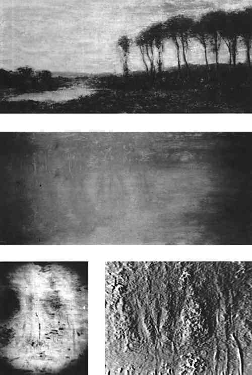
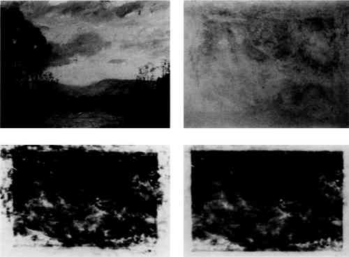
A major advantage of this technique is the instantaneous display of the radiographic image on a television screen. This means that the image may be evaluated for proper exposure and positioning factor while it is being obtained. A second advantage is the very fine spatial resolution that is possible with this imaging device, which is important if one is interested in small details in the images of the paintings. Current image intensifiers have the capability of showing details as small as 0.25 mm in size, allowing the display of fine detail in individual brush strokes in the painting. The major difficulty with the use of this imaging modality is the limited area that can be imaged at one time. The largest image intensifier currently available is only 14 inches in diameter. Thus, the examination of larger areas would require multiple exposures. This system is thus useful for the detailed analysis of a small painting or a portion of a large one, while other digital techniques described subsequently in this communication may be used for overall analysis of works of major size. The digital imaging techniques offers new nondestructive ways to evaluate a painting as well as to compare the components of the work, the artistic technique employed, and the condition of the work. The digital fluroscopic images in Figure 2 show an example of one of the more common techniques of computer image processing, known as subtraction. If two
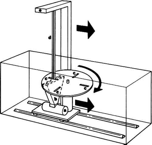
Other possibilities for this subtraction technique include energy and temporal subtraction. Energy subtraction is based on the well established fact that the attenuation properties of all materials are functions of the energy of the incident x-ray beam. The ability to perform subtraction using digital radiographs obtained at two different x-ray energies may provide additional information in the analysis of paintings. For example, two different pigments may have attenuation characteristics which are nearly identical at a given x-ray energy, making it difficult to differentiate between the two on the basis of contrast in a single image. However, the energy dependence of the attenuation of the two pigments may differ, allowing enhanced contrast by energy subtraction. Temporal subtraction involves the use of two images obtained at different times, with the interval ranging from seconds to years. It may be used to study the deterioration of paintings with time, since only the changes in the attenuation pattern will be displayed in the subtracted image. Further, it could be useful in the authentication of paintings. A digital image of a painting obtained and stored could at some later date be subtracted from a similar image of a suspected copy. Any difference between the two would be exaggerated, making identification of the painting from which the later image was obtained relatively simple and quite precise. 2 Scanned Projection RadiographyOne of the outgrowths of modern computed tomographic (CT or CAT) scanning instrumentation is a method for performing digital radiography which has many of the features of an ordinary radiographic study but in which each data point (“voxel” or small rectangular portion of the painting) is recorded in a discrete, finite manner.5 This technique is often called the “scout view.” At present, it is available in any hospital radiology department with computed tomography equipment. The method consists of placing the x-ray tube and detector assembly in such a position that the painting may be moved linearly through the x-ray beam (Fig. 3). As it is moved, data are collected by the computer from the detector array, and the image of the painting is thus stored in computer memory for subsequent manipulation and display.
The collected image, with or without digital processing, is displayed on a video monitor. In this image, the intensity of each individual point (“pixel”) in the image is proportional to the quantity of x-rays passing through the corresponding point in the painting. The spatial resolution of this system is acceptable but not as good as that obtained by digital fluoroscopy. A major advantage of the scanned projection technique is that x-ray energies over a wide range may be used. This is possible because the electronics of the detector array can be optimized for the x-ray energy being employed. This calibration procedure is not available for either conventional radiography or digital fluoroscopy. Large fields-of-view are also possible (Figs. 4 and 5). The equipment is expensive ($800,000 to $1,200,000), but is widely available in major medical centers. We have had
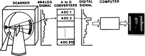
The scanned projection images in Figures 4 and 5 demonstrate a second common technique of digital image processing known as “windowing.” Image intensity, or “brightness,” using this equipment is measured on an arbitrary scale in units called Hounsfield units (HU). For the typical machine, the dynamic range is −1024 to 1024 (or more) HU, where −1024 is assigned to the attenuation of air, 0 to water, and 1024 (or the equipment maximum) to the densest material in the subject. If the entire dynamic range of image intensity is displayed simultaneously, the contrast resolution is low, as in film radiography. However, the windowing technique allows the viewer to select only a portion of the dynamic range for display at any one time. For example, in Figure 5C, the window center is −445 HU, and its height is 61. That is, in this 3 Scanned Point Source SystemA third digital radiographic method is the “flying spot” or scanned point source system.6 In this system, the x-ray image is formed by scanning a fine pencil beam of x-rays over the area being imaged (Figure 6). After passing through the object, the
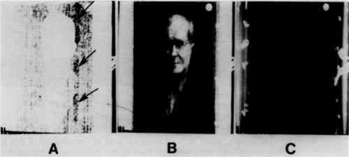
This technique has not been generally available because, until recently, the imaging time was of the order of fifteen seconds, and the spatial resolution was significantly less than with other methods. Although these time and resolution limitations are not so important in radiography of paintings, they are in clinical circumstances. Thus, these machines have not been widely employed in medical facilities. At present, images can be obtained with resolution of about two line pairs per millimeter. In addition, images can be stored and repeated images of the same area can be summed to provide higher quality pictures. Data can be manipulated to change contrast and other characteristics as for the other systems of digital radiography. This technique has not as yet received sufficient use to permit us to evaluate it and to compare it with the other two more widely accepted computer methods. REFERENCESBridgeman, and C. Keck, S.1961. The Radiography of Paintings. Rochester, New York: Eastman Kodak Co.. Price, Ronald R., Rollo, F. David, Monahan, W. Gordon, and James, A. Everette, eds.1982. Digital Radiography: A Focus on Clinical Utility. New York, New York: Grune & Stratton, Inc. Kruger, R. A., Mistretta, C. A., Lancaster, J., et al. 1978. “A digital video image processor for real-time x-ray subtraction imaging,” Optical Eng.17, 652–654. Nudelman, S., Capp, M. P., and Fisher, H. D. et al. 1978. “Photoelectronic imaging for diagnostic radiology and the digital computer.” Proc. SPIE, 164, 138. Brody, W. R., Macowski, A., and Lehmann, L., et al. 1980. “Intravenous angiography using scanned projection radiography: Preliminary investigation of a new method.” Invest. Radiol., vol. 15, 220–223. Tateno, Y., and Tanaka, H.1976. “Low dosage x-ray imaging system employing flying spot x-ray microbeam (Dynamic Scanner).” Radiology, vol. 121, 189–195.
 Section Index Section Index |