A TECHNIQUE FOR STRETCHING AND FRAMING A DOUBLE-SIDED CANVASBarry R. Bauman
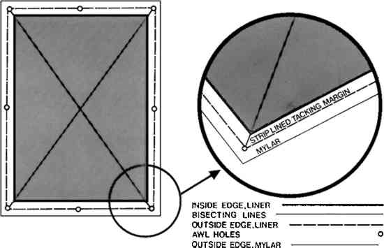
ABSTRACT—The conservation of a canvas that has been painted on both sides presents certain difficulties. The author discusses a stretching and framing technique for a double-sided canvas that incorporates a controlled spring mechanism connected to a movable frame liner. The overall effect of this method insures continuous canvas tension, as well as uniform tension to both warp and weft. The conservation of a canvas that has been painted on both sides presents certain difficulties. Cleaning, structural repair, stretching, and framing require alteration of standard conservation practices. This paper focuses on a stretching and framing technique for a double-sided canvas that incorporates a controlled spring mechanism connected to a movable frame liner.1 The canvas in question was painted with the same image dimensions on both sides. It had been previously stretched by attaching the tacking margin to a wooden, four-membered stretcher. This resulted in a significant amount of original paint being hidden underneath the stretcher support. In order to re-stretch the canvas so that both sides could be viewed in their entirety, the following methods were used. The canvas was placed stretcher-side up on a table. The tacks were removed from the tacking margin and the old stretcher was removed. The tacking edges were dampened with wet cotton and flattened under weights. The margin was then edge-lined with natural Belgian linen using a wax-resin adhesive.2 To register properly a gilded liner that would be correct for both sides of the canvas, certain techniques were used. First, two liners 1″ wide and 3/8;″ deep were cut to fit the sight size of the paintings. One liner was stapled at its corners to hold the four members temporarily together. A T-square was used to assure 90� corners. A piece of mylar was placed on top of Painting A. A metal ruler was used to draw a line on the mylar connecting two diagonal corners. This was repeated for the two other corners. Thus, the mylar had a large “X” drawn on it, its lines corresponding to the bisecting lines of each corner. The stapled liner was then placed on top of the mylar so that its inside corners were also bisected by these lines. When aligned, the inside edges of the liner were drawn on the mylar. Small awl holes were made through the mylar and the lined tacking margin at the outside corners of the liner. Similarly, the outside mid-point of each side was marked. The canvas then was turned over, and the mylar was placed on top of Painting B. The holes in the tacking margin were registered with the corresponding holes in the mylar. At this point, it was possible to ascertain how the measured position of the liner on one side of the canvas would relate to the sight size on the other side. It was as if both sides of the canvas could be viewed at the same time. This registration technique is illustrated in Figure 1.3
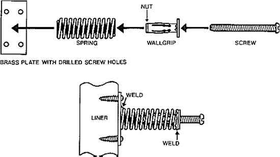
The staples were removed from the liner. One side of the liner was positioned under the strip-lined edge so that the awl holes corresponded to its mid and end points. Copper tacks were used to attach the strip-lined edge to the liner member. An adjacent side to this attached member was fitted into place and tacked. This procedure was repeated for the remaining two members. A mechanism for stretching the canvas and joining the two identical liners was fabricated from simple hardware items.4 A 1/8;″, extra small, star wallgrip was welded to one end of a medium gauge spring 1-�″ long and �″ in diameter.5 A wallgrip is a metal cylinder, with a nut at one end and a washer at the other, through which a screw can be inserted. A thin brass plate, 1″ long and �″ wide, was welded to the other end of the spring. Screw holes were drilled into the brass plate just inside of each corner. The liners were joined by inserting �″ No. 3 wood screws through the holes in the brass plate and into the sides of the liners. Three mechanisms were attached to each side. These items, separate and joined, are shown in Figure 2.
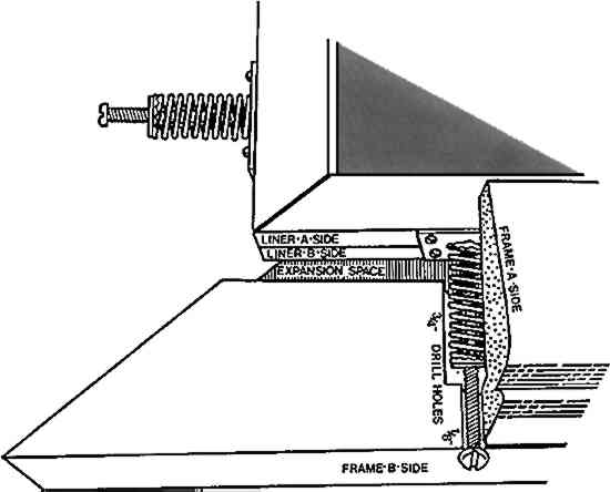
Two identical frames were constructed with certain features.6 First, the molding had to be at least as wide as the length of the spring mechanism. An aesthetically pleasing 3-�″-wide molding was chosen by the owner. The rabbet had to be cut and sanded to accommodate expansion and easy movement of the liners. Holes, 2″ long and 3/4;″ in diameter, were drilled in the appropriate positions to contain the springs. A second hole, 1/8;″ in diameter, was necessary for the adjusting screw. This was drilled from the outside of the frame to align with the center of the spring. With the mechanisms in their respective positions, the two frames were joined, top and bottom, using brass mending plates. The adjusting screws were inserted into the outside holes until contact was made with the nut at the end of the wallgrip. By evenly tightening the screws, the liners and the spring mechanisms were pulled towards the outside of the frame, ultimately stretching the canvas to the desired tension. As a finishing touch, the countersunk screw heads were painted to match the dark tone of the frame. A schematic illustration of the assembled frame is represented in Figure 3.
In addition to fulfilling basic stretching requirements, this technique offers further benefits. Under varying conditions of heat and relative humidity, the spring mechanisms will adjust and continue to provide even canvas tension. And most importantly, this method offers uniform tension to both warp and weft, as opposed to other methods which induce uneven tensions through corner expansion. REFERENCESThe two pictures were painted by William Zorach (1888–1966) and measure 29�″ high and 35� ″ wide. They are from the collection of Mr. Marshall Field, Chicago, Illinois. The wax-resin formula was 2 parts microcrystalline wax (Multiwax-W445, Witco Chemical Company), 1 part paraffin, and 1 part Zonorez 7085 (Conservation Materials, Ltd.). All illustrations drawn by Mr. Steve Rockwell, Glen Ellyn, Illinois. Welding performed by Ms. Janice Stevenson, Chicago, Illinois. Springs obtained from ICA Stretchers, Oberlin, Ohio. The liners and frames were made by Mr. Fred Baker of Frederick's Frame Studio Inc., Chicago, Illinois.
 Section Index Section Index |