THE RECOVERY OF COLOR IN SCORCHED OIL PAINT FILMSChristopher Tahk
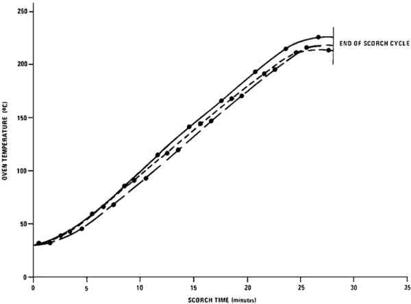
1 EXPERIMENTALPAINT SAMPLES were prepared from the commercial artists' oil tube colors listed in the Appendix.9 To obtain paint consistency suitable for layer preparation, the white samples were diluted with 15% of their weight by a 1:1 (v:v) mixture of linseed oil:turpentine.10 Each of the colored paints was thoroughly blended with 115% of its weight of the zinc white paint containing 35% of its weight of the 1:1 linseed oil:turpentine mixture. The paints were spread over one surface of 2 � 2 in., 0.5 mm thick aluminum panels using a 127 μm thick Mylar mask with a microscope slide as a drawbar to produce paint layers of an even thickness about equal to that of the mask. Prior to use, the coated squares were allowed to dry for three months under normal room lighting (indirect fluorescent lamp illumination for about twelve hours per day) while shielded from dust. Scorching of the paint samples was carried out in a laboratory oven11 equipped with an auxiliary heater and an internal fan to keep temperatures approximately equal throughout the oven chamber. Iron-Constantan thermocouples were used in conjunction with a strip-chart recorder to monitor temperatures at three different oven locations. The range of scorching conditions that caused color changes in the paint film but which did not carbonize the paint was determined empirically. One of
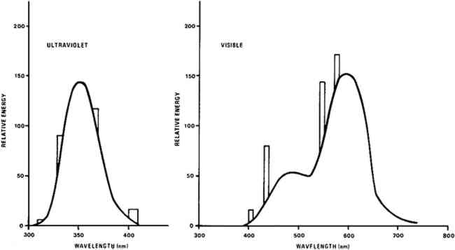
Light bleaching was effected under either a bank of General Electric (G.E.) 100 watt F84PG17-CW Power Groove Cool White fluorescent lamps or under a bank of G.E. 40 watt F40BLB “black light” lamps emitting in the near ultraviolet. The fluorescent light bank incorporated a one-eighth inch thick sheet of Rohm and Haas UF-3 Plexiglas which removed virtually all ultraviolet radiation emitted by the lamps. The typical spectral energy distribution of each lamp type, that of the cool white lamp corrected for the UF-3 filtration, is given in Figure 2.12 The measured intensity of the light from the visible light bank incident upon the paint samples was approximately 40,000 lux,13 about four hundred times greater than that on paintings on exhibit in many museums. No direct intensity measurements were made on the radiation produced by the long wavelength ultraviolet light bank. But, as these BLB fluorescent tubes have the same efficiency as an ordinary visible light producing fluorescent tube, about 22%,14 the intensity of the total radiant energy incident upon paint samples under the ultraviolet lamp bank is no more than 40% of that on samples under the bank emitting in the visible.
Environmental variables were not controlled during the experiments. Approximate ambient conditions, however, included temperatures of 25–30�C. and a relative humidity range of 55–75%. During bleaching the paint samples became only slightly warm to the touch. The paint sample layers were characterized by their diffuse reflectance spectra15 in the visible (375–750 nm) range as recorded with a Bausch and Lomb Spectronic 600 Spectrophotometer with an integrating sphere reflectance head. Measurements were made with instrument slit widths set to pass a 5 nm wide spectral band. Barium sulfate was employed as the reflectance standard. Use of a specially designed sample holder insured that each reflectance measurement on a given sample was always taken on the same part of the sample surface. The full reflectance spectra are not given here, but rather only the percent diffuse reflectance values at each of the three wavelengths of the three primaries of the 1931 CIE R,G,B color system: R (red), 700 nm; G (green), 546 nm; B (blue), 436 nm.16 Reflectance values at these three wavelengths serve as a gauge of the color of the paint. Only the three initial reflectance figures for each unscorched three-month-old paint layer are given as such: all others are presented as percentages of the initial reflectance value obtained on a given sample at a given wavelength, i.e., as relative diffuse reflectances. Recovery of original color through bleaching of a paint sample would result in all three relative diffuse reflectance values returning to 100%. |