THE CONSERVATION OF A PLASTIC MASK BY MARISOLW. T. Chase
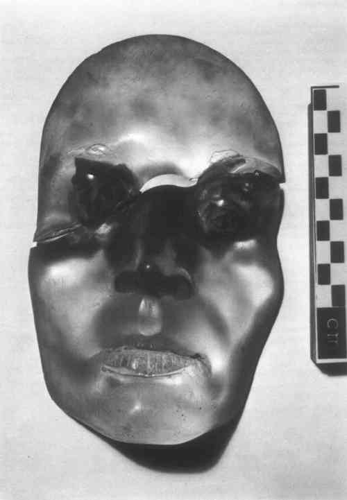
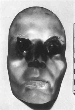
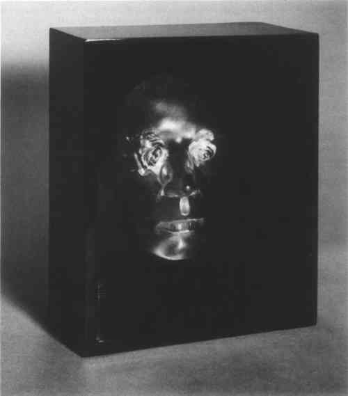
ABSTRACT—A life-size plastic mask with roses in place of eyes was received broken, split into two parts horizontally across the bridge of the nose. After the plastic material had been identified as a styrenated alkyd resin, the mask was repaired using a commercial resin similar to the original material and a novel gluing procedure. The surface was refinished where necessary and a new method of mounting was developed to secure the mask in its box. 1 THE MASK AS RECEIVEDTHE MASK is a life-size cast of a face, frontal, extending to just behind the cheekbones (Fig. 1). It is made entirely of a clear plastic, with the exception of the eyes, which are made from faded white roses. The roses are submerged below the surface of the plastic. The mask was mounted in a black, shiny, wooden box. While the mask was sitting on a shelf in the owner's house, it came loose from the wooden box and fell onto the floor, breaking diagonally across the bridge of the nose. The break extended from just above the proper left eye to just below the proper right eye, and ended at the top of the right cheekbone.
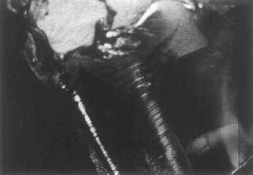
The owner brought the mask in to the Freer Gallery of Art Technical Laboratory on March 5, 1973 for examination and possible repair. It looked like an interesting, almost insoluble problem, and for this reason we agreed to take it on. The break was in a very visible area on the mask; to be acceptable, the repair would have to be nearly invisible. It was obvious from the outset that a special repair method would have to be used. We started experimental work on the mask simultaneously with attempts to find out anything about its method of manufacture or possible methods of repair. The artist who made it, Escobar Marisol, was, in 1973, selling through the Sidney Janis Gallery in New York. We sent letters to her through Sidney Janis and received no response. A member of our staff visited the gallery on a trip to New York and found out that the mask was quite old and had been sold by another gallery before Marisol began her association with Sidney Janis. One of the Janis Gallery workers asked Marisol about the mask and was not able to get any useful information. Marisol did not recall much about the mask, and she did not think that it could be fixed. 2 EXPERIMENTALFIRST, several photographs were taken of the glassy fracture in the plastic, using our Zeiss Epitechnoscope (Fig. 2). Small samples of the plastic were removed under the stereomicroscope and solubility tests were made. The plastic was not soluble in naphtha, slightly soluble in toluene, readily soluble in MI2 solvent mixture (toluene 70%, ethanol 10%, ethylene dichloride 10%, cellosolve 5%, cellosolve acetate 5%), and soluble in ethylene dichloride.
A small sample was removed from behind the proper left eye for identification by infrared spectrometry. The sample was sent to the Conservation Analytical Laboratory of the Smithsonian Institution (CAL no. 1538) and was found to be a styrenated alkyd resin (Fig. 3a). After some thought about what resins might have
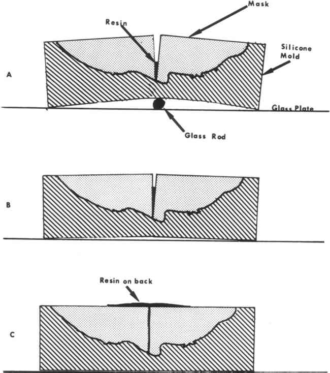
3 FABRICATION OF THE MASKTHE MASK had apparently been cast in one piece out of resin. The rose stems protruded slightly from the back. The roses might have been held by their stems during the casting and the stems later cut. A large hole (approximately �″) had been drilled into the mask behind the nose, to enable it to be attached to a stub protruding from the box. From its profile (see below) the hole looked as if it had been drilled with a Speedbore bit, commonly used for making large holes in wood. The front surface of the mask had a rough polish with a number of scratches in it, as did the back. 4 DEVELOPMENT OF REPAIR TECHNIQUEIT WAS OBVIOUS from the start of our examination that the glue line of the repair would have to be practically invisible. We had the additional problem that the rose petals were intersected by the fracture line, and they would have to be correctly aligned for an aesthetically satisfactory repair. The first step in the development of a repair process was to make a small cast block of Clearcast resin with a faded white rose in it (the rose came from W. T. C.'s garden). The resin was mixed with a hardener according to the directions on the container and allowed to set for three days. The aluminum foil, which had served as an outer mold, was then removed. The cast block looked rather similar to the mask. It was allowed to cure for sixteen more days, and then was broken through the center after having been sawn lightly along three edges to control the direction of the break. The actual break was made by hammering on a chisel stuck down in one of the saw kerfs. The test object broke directly through the rose, and the break looked very similar to that on the Marisol mask: it had a satiny surface with conchoidal fracture lines. To make an invisible glue line, the refractive index of the adhesive would have to match the refractive index of the original resin. In addition to this, it would have to be flowed in without bubbles, as any entrapped bubbles would show up as silvery, reflective spheres or spheroids along the break line. This meant that the repair adhesive would have to be carefully run into the break, and would have to wet the entire break evenly. The adhesive would also have to be bubble-free. This meant that brushing the adhesive on or introducing it into the break by capillary action would probably not be satisfactory. We had to devise a method to insure complete and even filling of the joint. The method used was the following: first, the two pieces of the broken test block were placed together in register on a piece of wax on a glass plate. A dam was built around them and they were then invested by pouring silicone rubber within the dam over the piece. Dow-Corning Silastic RTV-G was the rubber employed. After allowing the silicone rubber to set overnight, the rubber and test piece were lifted from the wax, the rubber peeled off, and both test piece and rubber mold cleaned. Any mold flash from the silicone rubber which had run up inside the break was removed from the rubber mold with a scalpel and the mold flattened as much as possible in the break area. The test piece and the mold were then reassembled. The mold with the test piece in it was laid down on the table top with the open back facing up. A glass rod of about 1 cm diameter was placed under the mold where the break occurred in the plastic piece. With gentle hand pressure, the mold and test piece could then be sprung open to make a V-shaped aperture at the break (Fig. 4).
Clearcast resin was used for the repair. It was mixed for slow setting and vacuum degassed after mixing. The mold was spread open at the point of the break and the bubble-free resin flowed into the break, carefully avoiding bubbles. When the resin reached an even liquid level, the mold was slowly closed, driving the resin upwards into the break evenly and smoothly. The break was filled completely with the liquid resin and the excess allowed to flow out the back of the test piece. The resin was allowed to cure for two days before the repaired test piece was removed from the mold. On removal from the mold and polishing of one side it was found that the break line had almost entirely disappeared. A slight cloudiness could be seen along the break line, which was visible only on very close examination. This might have been due to entrapped dirt or some other phenomenon. A few small 5 REPAIR OF THE MASKREPAIR OF THE MASK began by checking the fit of the two pieces. It was not good. The rose petals on the proper right rose had come out of place when the break occurred, and would not allow the two pieces to fit together smoothly. These petals were slightly pared down with a scalpel so that the break would fit tightly. One mm. of petal was the maximum removed at any spot. At the end of this paring process a piece of carbon paper was used to detect areas which did not fit perfectly: these areas were also pared down with a scalpel until the two pieces of the mask fit together exactly. Both broken surfaces were cleaned and degreased with VMP naphtha. Areas of conchoidal fracture along the edge of the mask and areas of fracture in other spots where pieces had been lost were filled in with microcrystalline wax, (MultiWax 445), to establish a casting space for the Clearcast resin when it was later poured in. The break over the proper left eye occurred in the eyebrow which had been partially lost. This was also compensated by filling with microcrystalline wax. The repair on the left eyebrow can be seen in Figure 5a.
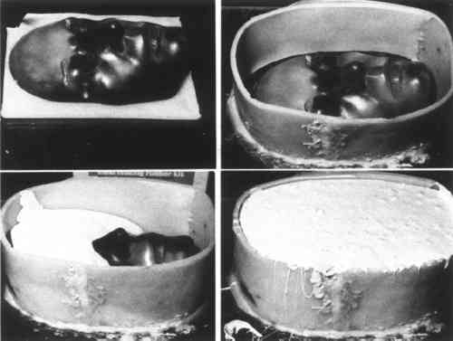
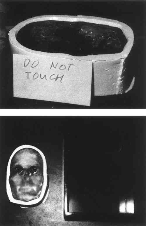
Wax was then slabbed and cut for making the enclosure to hold the mold. A wax slab was pressed onto a piece of plate glass, and the back of the mask laid onto it (Fig. 5a). A wax dam was then formed around the mask (Fig. 5b). Silicone rubber was then poured in. Three pounds of silicone rubber were used for the mold (Figs. 5c and 5d). The mold was allowed to set for four days before removal. The mask was removed from the mold; all of the wax fillings were then removed from the fractured and broken areas. VMP naphtha was used to clean these areas. The mold was carefully cleaned, and any mold flash which appeared on the break line was carefully pared down with a scalpel to flatness. The mask itself was cleaned again with VMP naphtha. It was set back in the silicone rubber mold and Clearcast resin mixed up, degassed, poured in and used to fill the cracks in exactly the same procedure employed on the test piece. The Clearcast resin was allowed to extrude upwards and over the back of the mask. Through the clear plastic of the mask some resin could be seen extruding onto some areas of the front, but we decided to leave it alone at this stage. This later proved to be a mistake; we should have protected the front and the back with some sort of masking agent (such as a silicone or a wax solution) where we did not want the resin to adhere. The repair was then allowed to set for an extended period (Fig. 6a).
In the meantime the box for the mask was cleaned and refinished with a commercial black lacquer. A hole was drilled in the center of the previous pin to locate the mask the box when it was remounted (Fig. 6b). The mask was removed from the mold after about four months of drying (setting). Excess Clearcast was cleaned off mechanically. The joint appeared to have mended quite well. A few small air bubbles and some slight filminess can be seen as on the test piece, but, in normal light, the break is almost invisible. Figure 7 shows the mask after repair but before remounting.
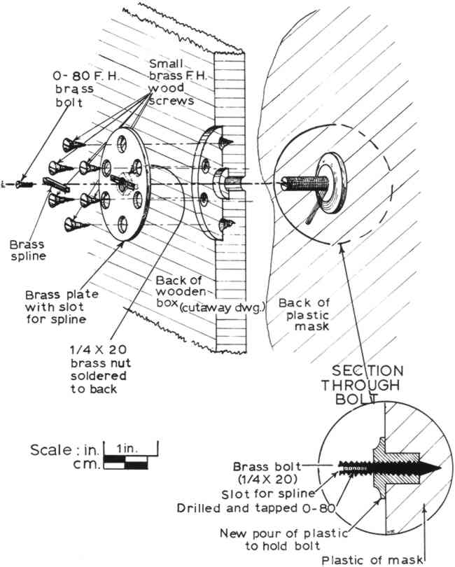
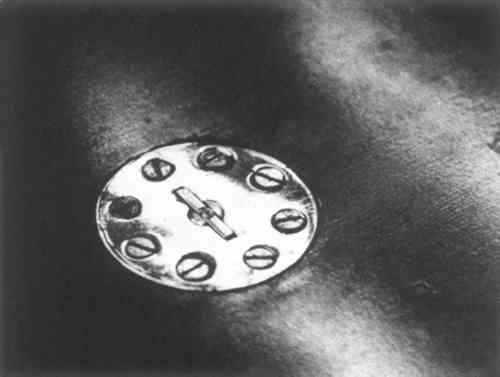
6 MOUNTINGSINCE THE CAUSE of the breakage of the mask had been the previous poor mounting into its box, it was decided to devise a new, more secure mounting method. These operations were again tested first on the test piece before being used on the mask; here we will describe only the mask. One thing that we found out in working on the test piece was that the Clearcast had considerable shrinkage when poured in thick sections; any holes to be filled with Clearcast should be overfilled. A bolt was mounted in a hole in the test piece and, after prolonged setting, the bolt was so well adhered that hammering on it would not remove it. Instead, the test piece broke along the mended fracture line when the bolt was very heavily hit. We decided to adhere a �″ brass bolt to the back of the mask. This would protrude through the back of the box and be secured by a round mounting plate with a nut in the center which would thread onto the brass bolt (Figure 8). The mounting plate would then have holes for wood screws so that it could not rotate in the back of the box and so that it would be adequately held there. A small brass spline would go across the bolt where it protruded from the mounting plate to stop rotation of the mask and to hold the
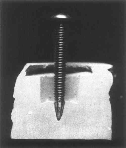
The interior hole in the mask for mounting was cleaned out and polished carefully. The hole was then filled with dental impression material (Alginate), which was removed after setting for one minute and a plaster positive made from the impression. The plaster positive was then sectioned so that the end of the brass bolt could be contoured to fit the hole exactly (Fig. 9). Both the interior cavity and the bolt were carefully polished. The bolt was then inserted into the hole and Clearcast poured around it; a wax dam had been built around the hole so that it could be slightly overfilled. After setting for a week the resin was hard enough so that the wax could be removed. The resin was then tooled down to the correct shape and polished.
The box was drilled with a number F drill (.257 inches) so that a little clearance would be allowed for the �″ (.250″) bolt. The back of the box was then milled to receive the plate. The mask was inserted into the front of the box, and the plate and nut, which had been soldered together, were screwed on from the back until they were flush. Positions for the wood screws were marked and the position of the spline was marked on the plate. The assembly was taken apart, the spline hole milled out, the spline made to fit, and a small (0–80) flat-head brass machine screw set through the spline into a threaded hole in the center of the �″ bolt (Fig. 10). This would hold the spline in place in its hole so that it could then hold the bolt in position in the mounting plate. After testing the entire assembly for fit, everything was polished and lacquered with Incralac, a methacrylate lacquer formulated with
ACKNOWLEDGEMENTSI WISH TO THANK the members of the staff of the Freer Gallery of Art, a number of whom assisted in various phases phases of this project. In particular, Dr. John Winter took photomicrographs and samples in the examination phase of the work, and his suggestions were of great help in devising the repair method. Ilona V. Bene and Steven Weintraub (at the time an intern in our laboratory) assisted in the repair; Mr. Weintraub did the final finishing of the surface after repair, a very patient and time-consuming job. The excellent photographs of the mask before and after repair were taken by Ray Schwartz and Jim Hayden of the Freer Photographic Department. Thanks go also to the Conservation Analytical Laboratory, Smithsonian Institution, and its staff member Walter Hopwood, who performed the infrared spectrometric analysis. I also thank the owner, who wishes to remain anonymous, for bringing this interesting project to our attention and allowing me to publish the treatment.
 Section Index Section Index |
