A TRIAL INDEX OF LAMINAL DISRUPTION1George L. Stout
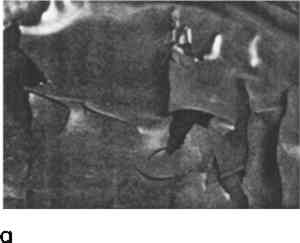
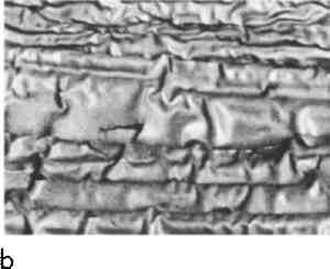
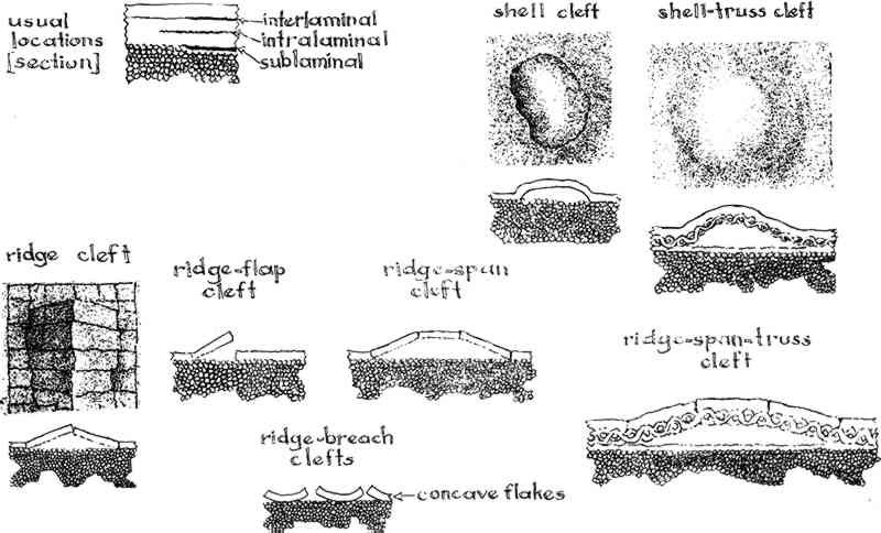
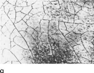
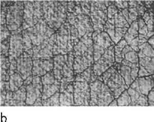
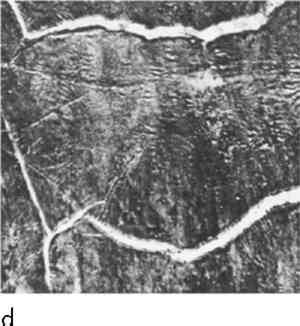
ABSTRACT—A scheme for describing this kind of degradation is suggested. Laminal disruption is a defect of a film, a thin cutting, or a coating which is an integral part of an artifact—paint, lacquer, marquetry, and enamel are examples. Disruption may lie parallel to the surface plane or contour: cleavage; it may run perpendicular to the surface: fissurage. Cleavage takes one of two general forms—shell clefts and ridge clefts. Fissurage also follows one of two types—rifts and crevices. The varied patterns that occur within these types can be described by terms that relate to the facts of their appearance. Several classes of artifacts depend on laminae for their meaning. A lamina is any thin substance—a film, coating, layer, or cutting—which is an integral part of the design. Such are paintings, lacquers, ceramic glazes, enamels, marquetry, and others. Laminae can break loose and be lost. If, disrupted, they stay relatively in place, the broken state distorts the content of a work. Notes on disruption are required in a record of condition. It is a destructive kind of degradation. It may also furnish evidence of identity. Description needs adequate terms if it is to be clear and complete. In an essay, “Prosthesis for Aphakia,” Richard D. Buck has written3. “A major contribution of 19th century scientists was the systemic terminology that is the basis of modern anatomy, botany, paleontology, and other sciences. It was a professional language, making use of Greek and Latin roots that could hurdle modern language barriers … [In conservation] we are now an emergent profession without a specialized language.” Laminal disruption has two large divisions: parallel, where the rupture occurs in the same directions as are held by the plane or contour of the artifact; perpendicular where the rupture occurs at right angles to the plane or contour. Parallel disruption may be obscure, hidden from sight even under changing reflections of light. It may be detected by sound but instruments and procedures for such detection have not yet come into general practice. Recent experiments have shown promise of more exact detection by halographic interferometry4 and by thermography.5 Parallel disruption where distinct is plainly visible as an irregular conformation, not related to the design, is particularly noticeable under changed angles of illumination. Whether obscure or distinct, parallel disruption is known as cleavage. When distinct it takes one of two forms: shell clefts of lenticular or bead shape (given such names as blister, bubble, air pocket, or air bell), and ridge clefts of angular or gable shape (given such names as buckle, tent, or cup). Shell clefts usually have rather shallow voids and are not always associated with perpendicular disruption. Those in Figure 5, 6 a and b, have crevices. A shelltruss cleft, as shown in Figure 1, is not uncommon. Its most likely occurrence is in paintings on panel where the ground contains a fabric and the cleft lies under the fabric, next or near the support. This may be obscure or distinct. If the laminate on the obverse of the cleft are firm and intact, the condition may not be very hazardous.
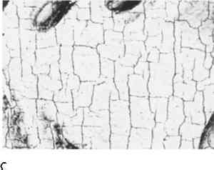
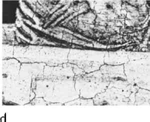
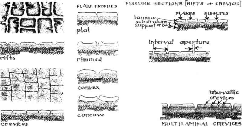
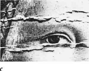
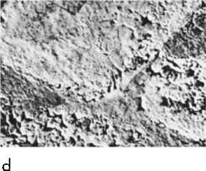
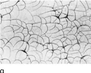
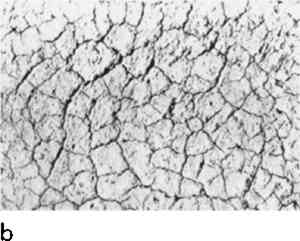
Depth of the void varies in ridge clefts, as shown in Figure 1 and Figures 5c and 5d, which are almost always associated with perpendicular disruption. An extension of the ridge cleft is the span cleft. Here the entire bond of the middle flake is severed from the sub-stratum and the flake is held in place only by contact at the edges. Exceptional circumstances of construction and environment may allow the spanflake to stay where it has been. Usually it will have fallen out and have left a lacuna. Perpendicular disruptions are fissures, as shown in Figure 2 and Figures 6–8. They have been given such names as cracks, crackle, crazing, and craquelure. Two types can be readily distinguished: rifts and crevices. Rifts tend toward a wide aperture, a depth of only one or two laminae, and a flake profile rimmed or convex. They often occur in areas of low value and hence may show a pattern higher in value than the adjacent tone. (An exception is seen in Figure 8a.) Crevices tend to be dark; they are often associated with ridge clefts; flake profiles are apt to be plat or concave; apertures are usually small in measure.
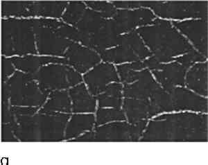
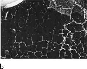
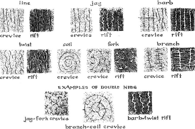
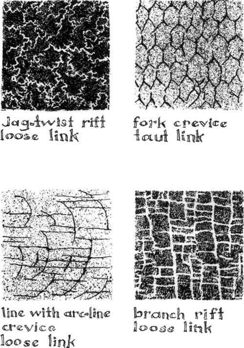
The profile or cross-section of fissures is familiar in the experience of conservators as are terms to describe it. Pattern, however, lacks a satisfactory scheme for denotation. An obstacle has been the inclination to seek terms which would explain or allude to the cause of the disruption. The cause may be hard to find. (It is highly improbable, for example, that an examiner could discover by observation the causes of the pattern in Figure 8,b.) Assumptions concerning cause tell nothing about how the pattern looks. Fissures in laminae can be seen plainly and can be given names related to what is seen. Another block in the way of reaching a descriptive scheme for patterns has been that otherwise great boon to documentary records, the photograph. Why be bothered with words when one can make a photograph? Of course one makes a photograph, an echo of what is seen, and one has got no nearer to defining the appearance and no farther towards an organized system which may lead to improved understanding. Rupture probably starts with points of weakness. These become evident when they extend into lines, as shown in Figure 3. Patterns are linear. In places the rifts or crevices are almost straight. They may be twisted or they may swing into arcs or coils. They may change direction within small measure and be jagged. They may sprout lateral prongs or barbs and these may reach as wide as branches. From a point fissures may run out in different directions and be forks. These are the nibs of pattern. It is common to find two or more nibs in one lamina and to find them run together in net or mesh linkages which may be taut or loose, as shown in Figure 4.
A further aspect of pattern in fissures is the secondary or enclosed system within a larger one. This usually occurs in multilaminal constructions. The fine fissures (named intervallic), as shown in Figure 2, may have a pattern slightly different from the larger ones that surround it. A prevailing direction of a linear pattern is frequent. That can be indicated by approximation to numbers on a twelve-hour clock dial: 4, from lower right to upper left; 6, vertical; 8, lower left to upper right; 9, horizontal. Customary adjectives will, of course, be added to modify all phases of description. Location of areas within an artifact is a requirement for describing this form of degradation as it is for all descriptions of a work and its condition. Standard methods of location would be an advantage. REFERENCESAt the annual meeting of A. I. C. in 1974 some suggestions were offered on this subject (Bulletin, 14, No. 2, pp. 9–14). A much revised version with the title, “Trial Description of Disrupted Laminae,” was on the program of the fifth annual meeting in 1977. The content was essentially the same as the presented here. 350 Sharon Park Drive, C-23, Menlo Park, California 94025. “Prosthesis for Aphakia,” Miscellanea in Memoriam Paul Coremans (1908–1965), Bulletin de l'Institut royal du Patrimoine artistique, XV-1975, pp. 36–39. Asmus, John F., Laser Research Project, program report to the National Endowment for the Arts, 1975, pp. 15–19.
Miller, Bruce F., “The Feasibility of Using Thermography to Detect Subsurface Voids in Painted Wooden Panels,” Journal of the American Institute for ConservationXVI, 2, pp. 27–35. ACKNOWLEDGEMENTSPhotographic illustrations, as shown in Figures 5–7, were provided through the courtesy of the following: Asian Art Museum of San Francisco (The Avery Brundage Collection) abbreviated as AAM of SF; Isabella Stewart Gardner Museum, Boston, ISGM; Prof. Sheldon Keck, Cooperstown Graduate Programs, Cooperstown, New York, KECK; and Teri Oikawa-Picante, Conservator, The Fine Arts Museums of San Francisco, T O-P. Thanks are gladly recorded for these many favors.
 Section Index Section Index |