THE FEASIBILITY OF USING THERMOGRAPHY TO DETECT SUBSURFACE VOIDS IN PAINTED WOODEN PANELSBRUCE F. MILLER
ABSTRACT—Thermography is a technique whereby the construction or condition of objects is studied by means of precisely measuring temperature variations over the surfaces of such objects. Voids within solid structures tend to cause cold or hot spots on the surfaces of these structures as the whole object is heated or cooled slightly. Industrially, thermography is used to detect voids in cast and laminated structures. By studying areas of known voids in test panels, the described research indicated that voids as small as 1/8″ in diameter beneath the gessoed surfaces of wooden panels could be resolved with a raster scanning radiometer, the principal instrument used for thermographic studies. Smaller voids were discernible when they were grouped together. Only voids immediately beneath the gessoed surfaces of the test panels were detectible. Additional tests indicated that areas of simulated cleavage between the wood support and the gesso layers on the test panels could be detected thermographically. 1 INTRODUCTIONThermography is the technique whereby the structure or condition of objects is studied by means of precisely measuring temperature variations over the surfaces of such objects. Research was undertaken to determine whether thermographic techniques could be applied to the field of art conservation to detect subsurface voids within painted wooden panels. It must be stressed, however, that this research was carried out as a feasibility study with no attempt being made to establish or refine a technique that could be immediately applied to the examination of works of art. Blind cleavage and worm tunneling are two manifestations of the deterioration of panel paintings that can be difficult to detect. The term cleavage refers most often to a loss of bond between two paint layers, between a paint layer and the ground layer, or between the ground layer and its support. Blind cleavage is simply a form of cleavage that cannot be detected visually. Worm tunneling is the condition affecting panel paintings wherein insects have consumed either the gesso ground or the wood support beneath the gesso, thus leaving the paint layers unsupported. Even if the appearance of the reverse of a panel indicates that it had been attacked by insects, it is often difficult to determine whether insect damage is present immediately beneath the paint surface that is the location where the presence of any void would have the most serious effect on the security of the paint film. Because blind cleavage and worm tunneling have the potential of resulting in extensive damage to the design layers on panels, there is a need for a technique of detecting these defects. Presently the technique of “sounding” the paint surface is the chosen method for detecting blind cleavage and worm tunneling. Unfortunately, this technique is capable of detecting only large voids and the required contact with the paint surface can be extremely dangerous for an unsupported paint film. X-radiography has some potential for the detection of worm tunneling. However, the presence of x-ray absorbing pigments in the paint or ground layers would prevent the detection of small worm tunnels within a wood support. In addition, only sophisticated x-ray techniques have the ability to establish the exact location of worm tunnels within panels. X-ray techniques are not at present capable of detecting cleavage. An ideal method for detecting cleavage and worm tunneling should have the following characteristics, listed in order of importance:
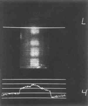
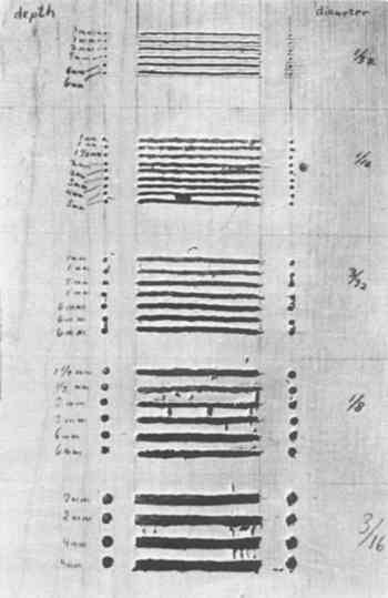
X-radiography and the technique of sounding do not satisfactorily meet the first three requirements. This being the case, the author feels justified in proposing another technique that has the potential to meet at least the first three requirements, if not all six. 2 THE THEORETICAL BASIS FOR THERMOGRAPHYThe thermographic detection of voids within solid structures is based on one simple principle. This principle is that the thermal coefficient of air is less than the thermal coefficients of wood and paint. Because air has a very low thermal conductivity, it has the ability to restrict the flow of heat. Because voids within panel paintings contain air, these voids can be expected to have insulating properties. The insulating effect of voids within solid substances can be illustrated by considering the following model: the heating of a metal bar that has a slot cut near its front surface and penetrating from one side of the bar to the other. This slot constitutes a void within the otherwise solid composition of the bar. If the front surface of the bar were evenly heated, heat would immediately begin to penetrate the bar and travel toward the back surface. The air within the slot, however, would locally restrict the flow of heat. The result would be that the front surface of the bar over the slot would retain its heat longer than the surrounding surface that is in contact with a relatively large mass of metal acting as a heat sink. By measuring the temperature across the whole front surface of this bar the location of the slot could be established. There are several methods of creating conditions by which temperature variations over subsurface voids can be produced. The back surface of an object rather than the front surface can be heated. Either the front or back surface can be cooled rather than heated, or any combination of these methods could be used. When dealing with art objects, however, any technique that requires marked changes in temperature is out of the question. The fact that voids have the capacity to induce temperature variations on surfaces would be useless if no means for detecting these variations existed. Although there are many instruments capable of measuring heat, few of these devices are suitable for void detection techniques. Although contact thermometers such as liquid in glass thermometers and thermocouples can be extremely sensitive and accurate, they are slow to react and difficult to read. It is also difficult to obtain an accurate temperature measurement of a small object with a contact thermometer because its mass (even the small mass of a thermocouple) often overwhelms the mass of the object being measured.2 This would be the case with unsupported paint films that have very low masses. It is also difficult if not impossible to simultaneously measure the temperature of many points on a two-dimensional surface with contact thermometers. Therefore, although contact thermometers are inexpensive and readily available, they are unsuitable for void detection techniques. Because of the unsuitability of contact thermometers, a remote temperature-sensing device was used for this research. The instrument used was a raster scanning radiometer. Raster scanning radiometers are similar to television cameras in that they optically scan two- or three-dimensional objects placed in front of them and produce two-dimensional images of these objects on a cathode ray tube (CRT). Whereas television cameras sense the visible light reflected by the object viewed, radiometers sense the infrared radiation emitted by the object. All matter with a temperature above absolute zero (−273�C) emits infrared radiation and because the intensity and wavelength of this infrared radiation is directly proportional to its temperature,3 the record of the emitted infrared radiation produced on the CRT of the radiometer can be directly translated into the temperature of the object. Radiometers are used in industry to measure minute temperature variations in electronic circuits, to detect voids in cast ceramic or metallic objects, and to detect disbonds in laminated structures. In medicine, radiometers are used to detect the minute local changes in body temperature caused by tumors and obstructions in arteries. The device used in the well-known research of J.R.J. van Asperen de Boer in which he studied underdrawings in paintings was done with a slightly modified infrared radiometer.4 The radiometer used for this research was a Spectrotherm Model 800 medical radiometer.5 The instrument was situated at St. Vincent's Hospital in Toledo, Ohio. This radiometer was sensitive enough to detect temperature variations as small as 0.2�C. The image produced by this radiometer is called a thermogram. Several thermograms, which in this case are Polaroid� photographs of the radiometer's display, are reproduced in Figures 1a through 1d. Each thermogram is an image of a painted wood panel constructed for this research. The light areas on the thermograms represent hot areas on the panels while the dark areas represent cooler areas. The graphs on the bottom of each photograph are graphs of the temperature variation across the image area beneath the fiducial marker, which can be set by the machine's operator to measure the temperature of any horizontal line in the image area. The horizontal axis of the graph represents the location of any thermal variation and the vertical axis represents the relative temperature of the area. The span of temperature measured by the instrument and represented by the graph can be adjusted; the chosen setting is recorded in the lower right corner of each thermogram. The “4�” setting means that from the top line to the bottom line on the graph, a temperature span of 4�C is represented, therefore, each line corresponds to 1�C. The “2�” setting means that each line represents 0.5�C. Thus each thermogram produced by this instrument contains not only a thermal “picture” of the object being measured, but also a graph of the temperature along a horizontal strip of the object providing more precise but still relative temperature measurements of the object.
3 EXPERIMENTAL PROCEDURES AND RESULTSAn essential part of the research was the use of test panels that contained areas of simulated cleavage and worm tunneling. By comparing the known construction of the panels with the thermographic results, the feasibility of the technique could be established for known conditions. Although a number of test panels were constructed and analyzed thermographically for the original research, the space limitations of this paper prohibit the description of more than two of the test panels and their associated thermographic analyses. Test panel D-4 was designed to determine whether or not thermography could detect voids within a wooden support (simulating worm tunneling) and what the resolution of the instrument is
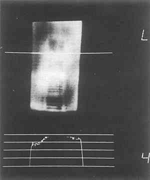
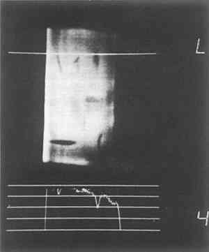
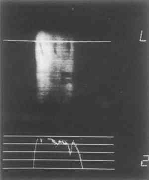
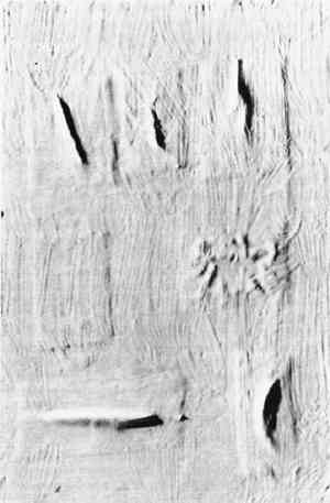
The thermographic studies of this panel made use of two heating techniques. The first technique was to suspend the panel from a steel frame 20″ in front of the radiometer and heat surface of the panel for ten seconds with a 250 watt infrared heat lamp. Figure 1a is a thermogram of the panel made ten seconds after the brief heating was completed. This thermogram shows all five groups of voids but they are poorly distinguished. Although the top group of voids, that with the narrowest grooves, does not show up well in this figure, it was discernible on the original and was slightly more apparent in other thermocouples made at the same time. The other heating method was to heat the panel evenly from the reverse. The heat lamp provided too little radiation to heat the entire panel from the reverse in a reasonable period of time. The only other source of even heating available in the hospital was a stream of hot air produced by an x-ray processing machine operating in an adjacent room. The temperature of this air was approximately 90�F (32�C). Figure 1b is a thermogram of the panel made one minute after the panel was removed from this source of heat. With this heating method much better resolution was obtained. Although the group of smallest voids is not at all visible, the individual grooves and adjacent holes can be differentiated in the last two groups. Thus, by heating the panel from the reverse, and with an object-radiometer distance of 20″, individual voids as small as 1/8″ in diameter could be resolved. The depths of the grooves, which ranged from 1 mm to 6 mm, did not affect their detectability. Panel D-1 was designed to simulate cleavage between the support and ground layer. To simulate such cleavage, patches of kraft paper were saturated with hide glue and adhered to a wood panel in such a manner that the paper was “tented” in the center of each patch. When the glue dried, six irregularly shaped oids had been produced beneath the paper patches. Gesso was applied over the panel and paper patches, and the dry gesso was coated with resin as well as was panel D-4. Figure 2b is a raking light photograph of the finished panel, and Figure 1c is a thermogram of the panel made one minute after the panel was removed from the flow of hot air that had heated it from the reverse. The sensitivity range of this thermogram was 4�C. The thermogram in Figure 1d was made one minute after Figure 1c, with a sensitivity range of 2�C. The dark images on the thermograms represent cool areas on the surface of the panel produced by the pockets of cleavage. Although the voids in this panel were apparent by visual examination and were also detectible by sounding, this experiment does indicated that thermography is capable of detecting simulated pockets of cleavage between the support and ground layers.
Another experiment was carried out to determine whether thermography could detect voids not directly beneath the gesso layer but deeper within the wood support. It was found that such voids are not readily detectible through thermographic analysis. This may be an advantage of thermographic analysis since only the most serious voids, those immediately beneath the paint and ground layers, are detectible. Anyone familiar with methods of infrared analysis is aware of the fact that different substances emit varying amounts of infrared radiation depending on their chemical composition, physical state, and other factors. This means that one object may emit more infrared radiation than another object even though both objects are at the same temperature. The amount of infrared radiation emitted by a substance is termed its emissivity.6 Large variations in emissivity might complicate the technique of detecting voids within panel paintings. It is possible that a small patch of paint with a high emissivity when surrounded To study this problem a number of experiments were carried out. First it was determined that artist's paints do indeed vary considerably in their infrared emissions. It was then determined that various varnishes, both natural and synthetic, have high emissivities. By applying strips of various varnishes over patches of oil paints with both high and low emissivities and studying this construction thermographically, it was determined that most surface coatings, especially dammar, mastic, and acrylic resins, have sufficiently high emissivities to mask or equalize variations in emissivity caused by pigments. In the electronics industry surface coatings have been applied to electronic components to equalize emissivity variations as large as 50:1.7 Thus if a painting contains a surface coating, emissivity variations will probably not be of great concern in void detection studies. From the experimental evidence it is apparent that thermography is a feasible technique for detecting subsurface voids in painted wooden panels. Individual voids beneath the gesso as small as 1/8″ in diameter were resolved and smaller voids were discernible when 4 DISCUSSIONBefore this technique is applied to works of art more information must be obtained. The maximum temperature change to which a panel painting can be safely subjected should be studied. Although much has been written about the importance of relative humidity in panel paintings, to the author's knowledge no data have been published on the effect of small and brief temperature changes on panel paintings when relative humidity is kept constant. Although the suggestion of warming or cooling panel paintings sounds somewhat ill advised at first hearing, one should remember that most panels, except those kept in scrupulously controlled environments, have probably undergone considerable and repeated temperature variations throughout their lives. Indeed, many necessary processes of conservation such as setting down cleavage and applying balsa backs often require the application of heat to panel paintings. It should also be considered whether or not a brief rise or decrease in the temperature of a panel is more or less desirable than rubbing one's fingers over the surface of suspected areas of cleavage or worm tunneling. For the sake of the art works subjected to future thermographic analysis, however, the minimum and optimum amounts of temperature change required to produce accurate images of subsurface voids should be determined. The heating methods used for this research were to a great extent dictated by convenience. Although the technique of heating the front surface of the panels was gentle, it did not produce adequate images of the voids. However, this technique may have the potential of considerable refinement. The method of heating the reverse of the panel provided better images but was more severe in that the panel was heated throughout its structure rather than just on its painted surface, and the temperature used happened to be 90�F. Although controlled studies at lower temperatures were not carried out, it is the author's impression that the required temperature change within the panel could be as little as 5�F to 10�F. By using heating and cooling techniques simultaneously, or by using short pulses of infrared radiation on the order of tenths of a second in duration, harmless but detectible temperature variations over voids might be created. Refinements in technique and information about minimum required temperature change must be determined experimentally, however. Unfortunately, the matter of cost must also be raised. Raster scanning radiometers are available from a number of manufacturers.8 Their costs range from roughly $27,000 to $40,000. However, for occasional thermographic studies of portable panels, a conservator may be able to use thermography equipment in hospitals as did this author. Because the major medical use of this equipment is the detection of breast cancer, possible methods of locating an instrument would be to get in touch with a local chapter of the American Cancer Society or to speak with someone working in the mammography unit in the radiology department of a large hospital. REFERENCESIntermuseum Conservation Association, Oberlin, Ohio, 44074; current address: Doerner Institut, Meiserstrasse 10, Munich, West Germany. Vanzetti, R.Practical Applications of Infrared Techniques: A New Tool in a New Dimension for Problem Solving. pp. 33–34. New York: John Wiley and Sons, 1972. Vanzetti, R. pp 11–14. VanAsperen De Boer, J. R. J. “Infrared Reflectography, A Contribution to the Examination of Earlier European Paintings.” p. 49. Amsterdam: Central Research Laboratory for Objects of Art. 1970. Spectrotherm Corporation, 3040 Olcott Street, Santa Clara, California 95051 Vanzetti, R. pp. 14–15. Burrowes, N. R. “Emissivity Equalization by Thermosetting Coatings.” Paper Read at the Spring Convention of the Society for Nondestructive Testing. February 1965, at Los Angeles, California. Distributed by the Society for Nondestructive Testing, Inc., Evanston, Illinois 60204. AGA Corporation, 550 County Avenue, Secaucus, New Jersey 07094; Barnes Engineering Company, 30 Commerce Road, Stamford, Connecticut 06904; and Spectrotherm Corporation, 3040 Olcott Street, Santa Clara, California 95051. ACKNOWLEDGEMENTSPreliminary studies of the feasibility of using thermography to detect voids in wooden panels were done with an AGA Thermovision� 680 radiometer (see reference 8) with the kind assistance of Dietrich Baeu, President of the AGA Corporation, Secaucus, New Jersey. Representatives of the Spectrotherm Corporation (see reference 8) were very helpful in supplying information on their instrument. The author's deepest appreciation goes to those members of the staff of St. Vincent's Hospital and Medical Center, 2213 Cherry Street, Toledo, Ohio 43608, whose time and assistance made the research for this paper possible and also enjoyable. Special thanks go to Barbara Applegate, Assistant Director of Public Relations; Stanley T. Pinsky M.D., Chairman of the Department of Radiology; Tony Ruiz R.T., Chief Technician; Sue Daroczy R.T.; and Mary Sepeda R.T. Thanks are also extended to Marigene H. Butler, Director of The Intermuseum Laboratory, Oberlin, Ohio, and Abraham Rosenzweig, Ph.D., Associate Head of the ICA Training Program, Oberlin, Ohio, for their perceptive editorial comments regarding this paper and the original thesis from which it was drawn.
 Section Index Section Index |