Analytical Techniques
Foundation for Advancement in Conservation
© 2008
Introduction
Conservators will find a seemingly endless number of analytical techniques in the conservation literature or may even have access to some of them themselves.
This tutorial covers the most common analytical techniques that are available to analytical chemists.
- Spectroscopy
- Chromatography
- Scanning Electron Microscopy
- The "X factors" (XRF, XRD, EDS)
Understanding analytical techniques requires a knowledge of basic atomic structure and chemical bonding. Organic Chemistry for Dummies by Arthur Winter is a useful information source.
Contents
This tutorial is divided into the following sections:
Please complete each section in order, as the information builds on that covered in previous sections. You can return to any section later.
Press Ctrl+Shift+F to search.
Learning Objectives
After completing this tutorial, you will be able to:
- Describe the kind of information you can learn about a material through different analytical techniques
- Understand how absorption of energy is key to gaining information from spectroscopic methods
- Recognize that chromatographic techniques are used primarily for separating mixtures of compounds
- Know which techniques destroy the sample and which do not
- Differentiate among the uses for x-ray techniques
Foreword
First of all we should be clear that the actual test procedure is only one of a number of important steps.
- Choosing the correct technique
- Preparing the samples
- Running the tests
- Interpreting the results
Of all the steps the last one, interpreting the results, usually takes the longest and is by far the most difficult.
Spectroscopy
In this section you will be introduced to:
- Ultraviolet/visible spectroscopy
- Infrared spectroscopy
- Raman spectroscopy
- Mass spectroscopy
These techniques are used to find out what kind of chemical structure a material has and any changes to it after treatment or aging.
_chloride.png)

Spectroscopy: Electromagnetic Spectrum
First of all we need to remind ourselves about the electromagnetic spectrum. Energy travels in waves. Each wave contains a quanta (packet) of energy. As the waves get shorter the energy gets higher.

Spectroscopy: Electromagnetic Spectrum
A simple diagram of the electromagnetic spectrum
Ultraviolet/Visible Spectroscopy (UV/Vis)

Spectroscopy: UV/Vis — Bond Energy
Long chain, organic molecules can have single, double and occasionally triple bonds. These all have different energy levels.

Alternating double and single bonds are called conjugated bonds. Energy increases from single, double, to triple bonds, but single bonds are much higher in energy than conjugated bonds.
Spectroscopy: UV/Vis — Conjugated Bonds
As the number of conjugated bonds increases their overall energy drops. Eventually, instead of having energy levels in the far/mid UV range, the molecule has energy levels in the near UV/visible light range. It can absorb UV or visible light and appears colored.

Retinal, a dark red molecule
Spectroscopy: UV/Vis — Obtaining Spectrum
UV-Vis spectroscopy is usually carried out on samples in the liquid phase.

Spectroscopy: UV/Vis — Measuring Color Change
In conservation UV-Vis spectroscopy can by used to measure color change during aging or chemical changes such as increased conjugation or crosslinking.
UV-Vis range spectrometers can measure the 200–1000 nanometer range of the spectrum. Below 200 nanometers, oxygen in the air absorbs the light, making measurement more difficult.
Spectroscopy: UV/Vis — Sample Spectrum

\(n\) = number of conjugated bonds
As \(n\) increases, the spectra move to lower wavelengths (lower energy).
Spectroscopy: UV/Vis — Summary
You have learned that:
- Molecules that have energy levels in the near UV/visible light range can absorb UV or visible light.
- UV-Vis spectroscopy is usually carried out on samples in the liquid phase.
- UV-Vis spectroscopy can be used to measure color change during aging or chemical changes such as increased conjugation or cross linking.
Spectroscopy: Infrared Spectroscopy (FTIR)
FTIR: Vibrations
This technique looks at the ways the atoms in a molecule move in relation to each other.
Although we draw diagrams of chemical bonds with rigid, straight lines,
C — C — C
It would be much better to imagine them joined with springs that allow the atoms to move (vibrate) in various ways.
FTIR: Origins
The Fourier Transform in FTIR refers to the mathematics used to sort out the spectra into something that we can use.
Joseph Fourier was a French mathematician who died in 1830. Before his mathematics could be applied to scientific techniques, however, the microprocessor needed to be available. Fourier transform takes the original spectrum, which looks like a chaotic mess, and transforms it into its individual components. The usual analogy is of taking a musical chord and separating out the individual notes.
By the way, Joseph Fourier also showed that the atmosphere could contribute to the surface temperature of the Earth (Greenhouse Effect).
FTIR: Vibration Energy
 The
energy a molecule uses to vibrate is in the same part of the electromagnetic spectrum as infrared. Each different molecule vibration will use a slightly different level of energy.
The
energy a molecule uses to vibrate is in the same part of the electromagnetic spectrum as infrared. Each different molecule vibration will use a slightly different level of energy.
FTIR: Energy Absorption
When a beam of infrared light is shone through a sample it causes the molecules to vibrate. These vibrations subtract some energy from the original beam.
By comparing the final beam to the original beam we can see how much energy has been absorbed by the molecule and in exactly which part of the spectrum.
In a hydrocarbon, these vibrations would absorb energy at around the 350 × 10-6m (the near infrared range).
FTIR: Functional Groups
In addition to the different vibrations, the mass of the atoms and the strengths of the bonds will also affect the energy levels involved.
A strong bond like O — H where the oxygen atom is attached to the light hydrogen atom will vibrate at a higher frequency (energy) than a C — C bond.
All of this could lead to very complicated spectra. Luckily chemists realized that most functional groups within a molecule will vibrate at specific frequencies and these could be recognized in the IR spectrum.
FTIR: Hooke's Law
If we think of two bonded atoms as two vibrating masses joined by a spring then their frequency will be given by Hooke's Law.
A strong bond (high \(K\)) connected to a light mass will vibrate at a high frequency.
O — H and N — H absorb energy at 3600–3200 cm-1.
\(\bar{v}\) = frequency
\(c\) = speed of light
\(K\) = force constant
\(\mu\) = reduced mass
\( \bar{v} = \frac{1}{2 \pi c}\sqrt \frac{K}{\mu}\)
FTIR: Reduced Mass Calculation
Reduced Mass \(\mu\): This is calculated from:
\( \mu = \frac{m_1 \times m_2}{(m_1 + m_2)}\)
Where:
\(m_1\) = relative atomic mass of the first atom × 1.66 × 10⁻²⁷ kg
\(m_2\) = relative atomic mass of the second atom × 1.66 × 10⁻²⁷ kg
FTIR: Ethanol Spectrum
Here is the spectrum of ethanol showing the O — H, C — H, and C — O stretches. Note the units of measurement.

FTIR: Units of Measure
Infrared spectra are measured in cm-1. This is called wave number. Wave numbers are the reciprocal of the wavelength. (How many wavelengths would fit in one centimeter?)
\(\text{Wave number } = \frac{1}{\text{Wavelength}}\)
The scale on the \(x\) axis therefore runs:

FTIR: Frequency Table
Frequency tables for functional groups can be found in any textbook on organic spectroscopy or analytical techniques. These are taken from Interpreting Organic Spectra by D. Whittaker.
The cm-1 scale runs from 4000 to around 600.

| Functional Group | Absorption range (cm-1) |
|---|---|
| N—H | 3500–3250 |
| CON—H | 3500–3000 |
| O—H | 3700—3200 |
| COO—H | 3200—2200 |
| C—H | 3100—2700 |
| C=H | 1850—1640 |
| Aromatics | 1600–1500 |
FTIR: Distinguishing Polymer Types
In this example of an FTIR spectrum, Lomax and Fisher (1990) used FTIR to distinguish between different methacrylate polymers. The different methacrylates show different peaks in the 950–100 cm-1 range.

FTIR: Summary
In this section you learned that:
- Molecular vibration energy is in the infrared part of the electromagnetic spectrum.
- Looking at how much energy has been absorbed by the molecule in which part of the spectrum helps to identify functional groups within a molecule.
- Infrared spectra are measured in wave numbers.
- Frequency tables for functional groups can be found in any textbook on organic spectroscopy.
Raman Spectroscopy
Raman Spectroscopy: Background

Raman spectroscopy is named after Chandasekhara Venkata Raman, an Indian physicist who died in 1970.
In this technique, laser light is shone on, or through, the sample and one specific part of the scattered light is collected and analyzed.
Like infrared spectroscopy, the inter-molecular vibrations are studied to find the chemical structure.
Raman Spectroscopy: Background
Raman spectroscopy is a complimentary technique to infrared spectroscopy. It has also proved to be very useful for inorganic analysis such as paint or varnish identification.
Since Raman spectroscopy is not affected by water in the atmosphere and needs a very small sample (less than 1 µ), it can be used with a microscope (Raman microscopy).
Raman Spectroscopy: Diagram

The much smaller amounts of
Raman scattered light on either side of the main (Raleigh) light are the ones collected in Raman spectroscopy.
Raman Spectroscopy: Challenges
Historically Raman spectroscopy had some difficulties which made it the "poor sister" of infrared spectroscopy.
Because the amount of light collected is so small, an intense light source was necessary. This became much easier when lasers operating in the visible region became available.
Unfortunately many colored samples fluoresce in this range and the weak Raman scattering is lost under the much stronger fluorescence.
Raman Spectroscopy: Challenges
Infrared lasers overcame this problem but the intensity of the scattering decreases as the wavelength gets longer so detection was difficult.
This final problem was solved with the advent of the ubiquitous desktop computer which could do the Fourier transform calculations very quickly.
Raman spectrometers can now produce a single spectrum, made from several individual, co-added scans.
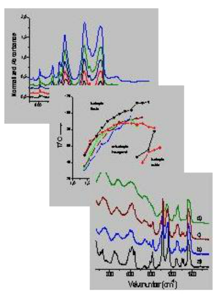
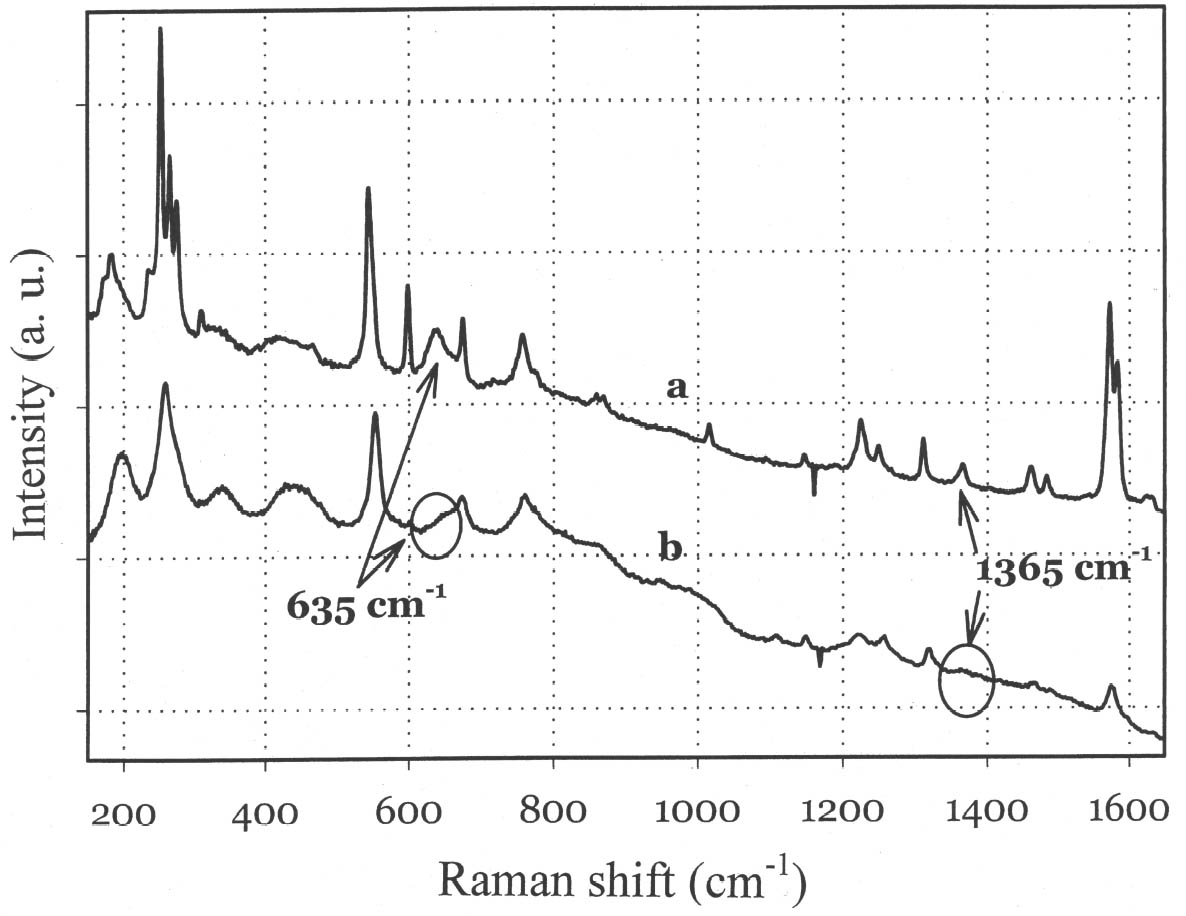
Raman Spectroscopy: Example
Here is an example of Raman spectra, in which Leona et al. (2004) compared the spectrum of pure indigo (a) with Maya Blue (b).
Raman Spectroscopy: Summary
You learned that:
- Laser light is shone on, or through, the sample and one specific part of the scattered light is collected and analyzed.
- Inter-molecular vibrations are studied to find the chemical structure.
- Raman spectroscopy is very useful for inorganic analysis such as paint or varnish identification.
- The spectra are not affected by water in the atmosphere and need a very small sample to acquire.
Mass Spectroscopy
This technique is unlike the three spectrographic techniques we have looked at so far.
Mass spectra are produced by bombarding the sample with electrons so that it splits into smaller fragments or ions.
UV-Vis, FTIR, and Raman are regarded as non-destructive techniques and the sample can be rescued and used again.
Mass spectroscopy destroys the sample and therefore should be classed as a destructive technique. Mass spectroscopy is often coupled with another analytical technique such as gas chromatography.
Mass Spectrometry: Fragmentation

Samples must be in the vapor phase.
The sample molecule M is bombarded by high energy electrons. It loses an electron and becomes a radical cation.
Mass Spectroscopy: Radical Cation
By losing an electron (negative charge) the original molecule gains an overall positive charge (a cation).
Losing one electron from an electron pair means that an unpaired electron is left on the molecule (a radical).
M·+
Mass Spectroscopy: Spectrum
The fragments are accelerated into a magnetic field which separates them according to their mass. The fragments with the lighter mass are deflected more by the magnetic field than those with heavier mass. This has the effect of spreading out the fragments when they hit the detector.

Mass Spectroscopy: Mass to Charge
Specifically they are separated by the ratio between their mass \(m\) and the charge \(z\).
\(\frac{m}{z}\)
Since the charge is usually 1 they appear on the spectrum as mass.
Mass Spectrometer: Diagram

Mass Spectroscopy: Decane Spectrum

Here we can see some of the fragments that split off from the whole molecule.
Mass Spectroscopy: Patterns
Molecules tend to split in certain, well defined ways. Long chain aliphatics, like the decane example, tend to lose methyl groups.
Carboxylic acids, CH3(CH2)nCOOH, will lose the acidic end group COOH.
Mass spectroscopy is very good for detecting functional groups. It can also be used for some elemental analysis.
Most of the calculation needed to identify fragments and from this to work out the identity of an unknown molecule is done by the computer. Scientists can buy "libraries" of mass spectra for comparison, or make their own by running examples of known chemicals.
Mass Spectroscopy: More Information
For anyone wishing to delve further into this technique (and gas chromatography) there is, at the moment at least, a tutorial managed by the University of Akron.
This site is copyrighted to James K. Hardy and the University of Akron. A link is provided on the web page for this tutorial. [Link is broken.]
Mass Spectrometry: Summary
In this section you learned that:
- Mass spectra are produced by bombarding the sample with electrons so that it splits into smaller fragments or ions.
- Mass spectroscopy destroys the sample.
- The fragments are accelerated into a magnetic field which separates them according to their mass.
- Molecular splitting follows particular patterns for different classes of organic compounds.
Chromatography
In this section you will learn about:
- High Performance Liquid Chromatography (HPLC)
- Gas Chromatography
- Thin Layer Chromatography (TLC)
These techniques separate complex mixtures into their component parts.
_and_330_nm_(B)_-_Molecules_2008,_13(9),_2220-2228.png)
Chromatography: Definition (HPLC or GC)
Chromatography exploits the differences in attraction between the sample and the mobile phase and the sample and the stationary phase.
The sample (analyte) is injected into a gas or liquid mobile phase which is passed over a solid stationary phase that has been packed into a column. The sample molecules are adsorbed/desorbed onto the stationary phase as the mobile phase carries them down the column. The smaller the affinity the analyte has for the stationary phase, the faster it will move down the column.
Chromatography: Diagram of Liquid or Gas Column

Chromatography: Resulting Chromatogram
The result of our simple experiment would look something like this.

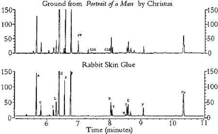
Chromatography: Gas Chromatography Example
In this example, Schilling et al. (1996) compared an unknown sample to the chromatogram of a known sample that they have run with the same mobile and stationary phases.
Chromatography: Thin Layer Chromatography (TLC)
This technique can be run with little or no dedicated equipment.
It is surprisingly accurate and is often used as a quick "look and see" method before more sophisticated analytical techniques are tried.
Conservators use it mostly to separate out the different components of dyes and inks.
TLC: Diagram of Set-up

TLC Supplies Description
The stationary phase is usually a thin layer of silica gel, aluminum oxide, or cellulose bound to an inert holder such as glass or plastic.
These are available at most chemical suppliers. The sample plates or plastic can be cut to size.
TLC Solvents
The choice of solvent, or solvent mixture, can be difficult. Usually a search of the conservation literature will tell you what other people have used.
A mixture of ethanol and water is a good starting point. For more advanced work the solvent classification list in Table 1 from Nyiredy, Sz; "Planar chromatographic method development using the PRISMA optimization system and flow charts" Journal of Chromatographic Science 2002, 40, 1–11 along with Figure 4 and the first part of the section "Selection of the individual solvents" should solve a lot of problems.
TLC: Photo of Set-up
A tiny amount of the sample (about the size of a period) is spotted near the bottom of the plate, which is then put in the solvent chamber. The solvent is pulled up through the plate by capillary action, taking the sample with it.

The original sample of black ink has separated into its component dyes.
There is a piece of blotter soaked in solvent to help saturate the container with solvent vapor.
Notice the container, the lid, the solvent.
TLC: Marking the Chromatogram
Once the plate is removed from the container the solvent front is marked, before it dries and disappears, and the top edges of all the components.

TLC: Comment on Marking Top Edge
Most, if not all, chemistry textbooks ask you to mark the center of the component rather than the top edge. This is fine if the component moves up the plate in a reasonably compact shape.
A lot of components will "smear" up the plate and it is difficult to decide where the center is.
TLC: Rf Values (Retardation Factor Values)
These are calculated for each component from the ratio of how far the component traveled versus the solvent front.

\(R_f = \frac{\text{Distance traveled by component}}{\text{Distance traveled by solvent}}\)
\(R_f \text{ of blue component } = \frac{b}{a}\)
TLC: Uses of Rf Values
Rf values are sensitive to:
- The solvent system
- The absorbent (grain size, water content, thickness)
- The amount of material spotted
- The temperature
There are no published tables of Rf values. Thin layer chromatography can be used as a:
- Comparative test (comparing one ink to another)
- Test of solubulity (seeing which component is most soluble in which solvent)
- Quick method of determining how many components are present in an unknown substance
TLC: Example
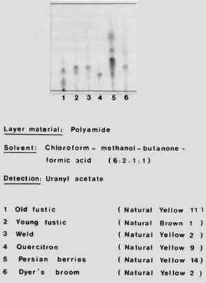
In this example Schweppe (1979) used thin layer chromatography to produce a reference chromatography of different natural yellow dyes. Notice that he has carefully listed the stationary phase (Polyamide) and the mobile phase (chloroform : methanol : butanone : formic acid 6:2:1:1).
Chromatography: Summary
In this section you learned that:
- Chromatography exploits the differences in attraction between the sample and the mobile phase and the sample and the stationary phase.
- While HPLC and GC require specialized equipment, TLC can be run with little or no dedicated equipment.
Scanning Electron Microscopy
In this section you will learn that:
- Unlike optical microscopy, SEM uses a stream of electrons which interact with the surface of the sample.
- The samples must be conductive in order to produce an image.
- Samples are usually covered in a very thin layer of gold in a sputter coater.
- Environmental SEM (ESEM) operates under a much lower vacuum and does not require gold coating the specimens.
Scanning Electron Microscopy (SEM): Definition
 Scanning electron microscopy has become a very common examination technique in conservation research.
Unlike optical microscopy, SEM uses a stream of electrons which interact with the surface of the sample.
SEM: Cost
Nowadays a scanning electron microscope is comparatively inexpensive (around $6000 at the moment). The technical upkeep however is expensive and unremitting.
Scanning electron microscopes are usually available for loan or hire at most universities.
SEM: Description

Electrons are produced by heating tungsten at the top of the column.
They are accelerated down the column and focused on the sample.
The column and the sample chamber have to be kept under high vacuum so that the electrons are not stopped by atmospheric gas.
The motorized sample stage carries the sample into the chamber and positions it under the electron beam.
SEM: Sample Preparation
 The samples must be conductive in order to produce an image. They are usually covered in a very thin layer of gold in a sputter coater.
Gold coating the specimens means that the sample can't be used for any other tests.
Some scanning electron microscopes, called environmental SEM (ESEM) operate under a much lower vacuum. In these systems it is not necessary to gold coat the specimens.
SEM: Diagram of Process
When the electrons strike the sample, several things can happen.

SEM: Sample Electron Micrograph
The primary backscattered electrons are used to determine different chemical areas or give information on crystalline areas. The x-rays are used for x-ray micro analysis (EDS). The secondary electrons are used to form the pictures we normally see in the literature.
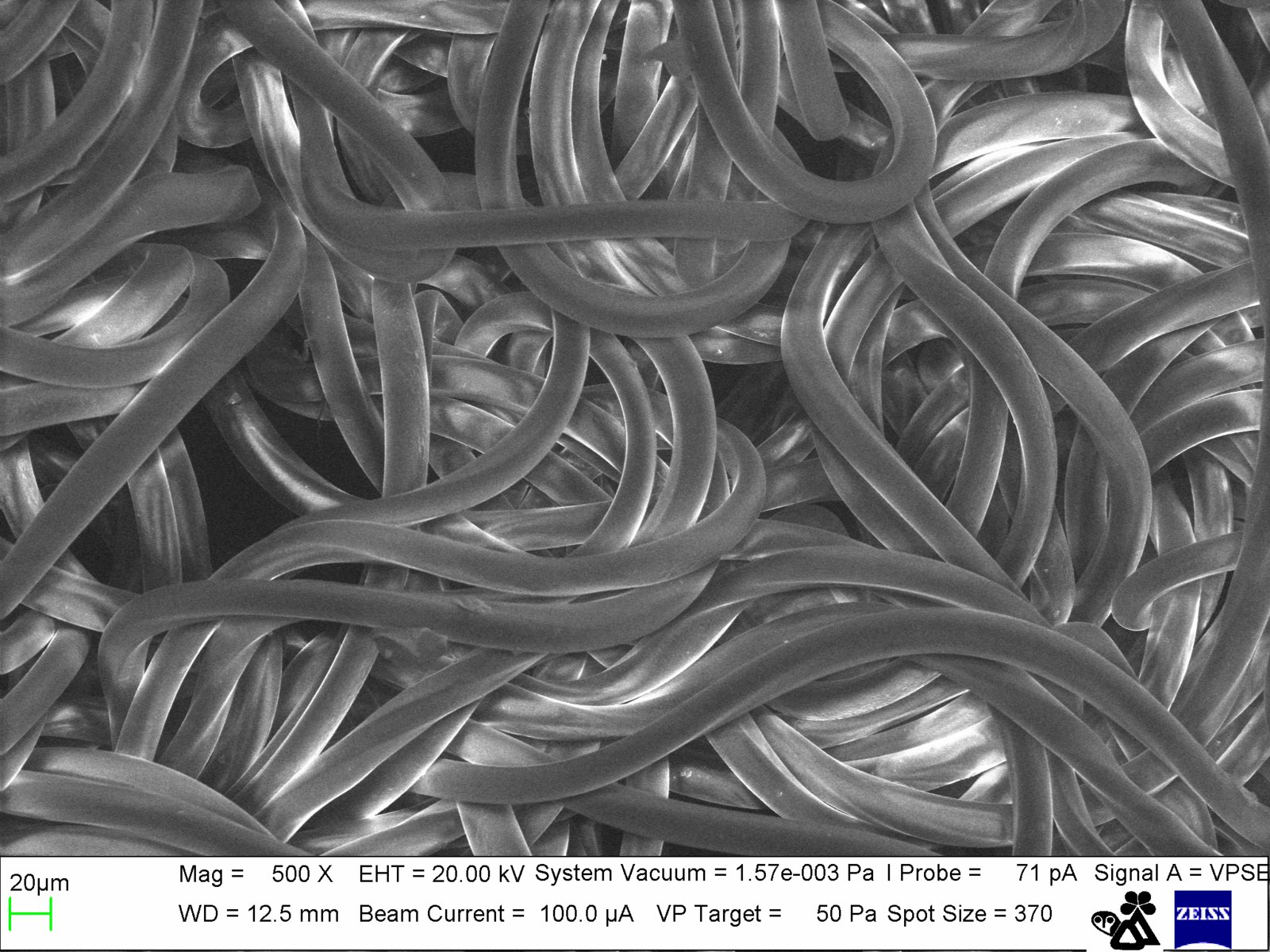
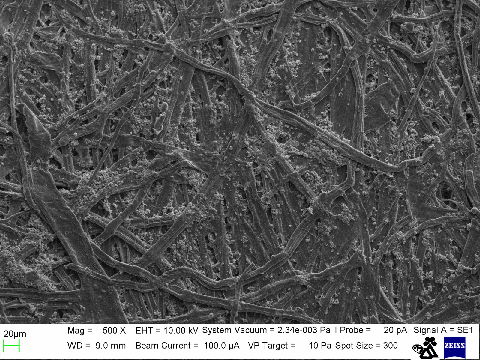 SEM images of synthetic nylon and cotton filter paper at 500x magnification.
SEM: Literature Example
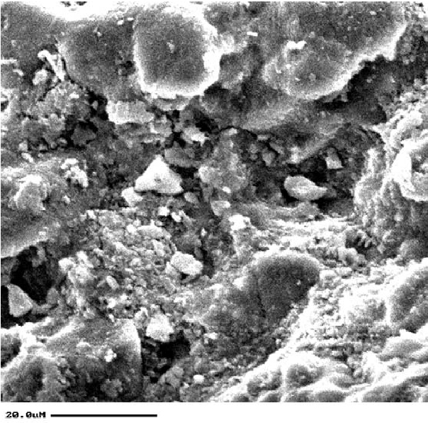
This is one of the many examples to be found in the conservation literature, Kavenaugh and Wheeler (2003) used SEM to examine the soiling of brickwork in a historic building.
Scanning Electron Microscopy: Summary
In this section you learned that:
- Unlike optical microscopy, SEM uses a stream of electrons which interact with the surface of the sample.
- The samples must be conductive in order to produce an image.
- Samples are usually covered in a very thin layer of gold in a sputter coater.
- Environmental SEM (ESEM) operates under a much lower vacuum and does not require gold coating the specimens.
The "X Factors" (XRF, XRD, EDS)
In this section you will learn about what I call "the X factor" techniques, which include:
- X-Ray Fluorescence (XRF)
(or Energy Dispersive X-Ray Fluorescence ED-XRF) - X-Ray Diffraction (XRD)
(or X-Ray Powder Diffraction) - Scanning Electron Microscopy Energy Dispersive Spectroscopy (SEM-EDS)
All of these techniques use x-rays to determine the elements present in an unknown sample or to examine the crystalline structure.
The "X Factors": SEM-EDS
Let's look at the last technique first since energy dispersive spectroscopy (EDS) is usually coupled with scanning electron microscopy (SEM-EDS). The electron cloud around a nucleus is arranged in "shells". The closer the shells are to the nucleus, the lower the energy of the electrons.

An incoming high energy electron interacts with an electron in an inner shell and displaces it leaving an empty energy level in the shell.
An electron in an outer, higher energy shell moves to fill the energy gap. In order to stay there it must lose energy in the form of an x-ray.
The "X Factors": SEM-EDS
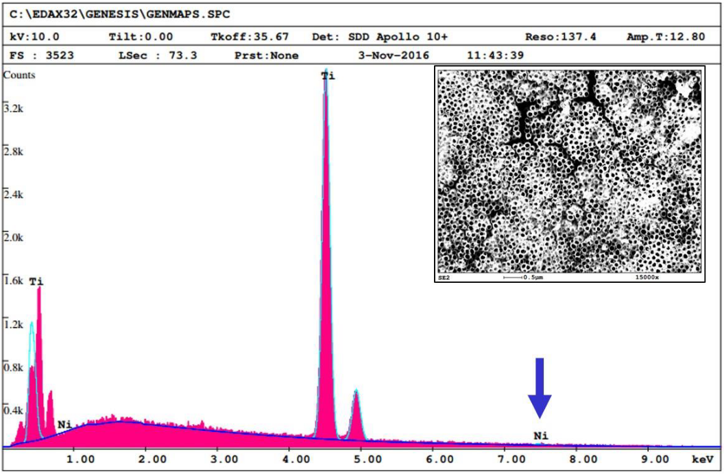 Since each element has its own, distinct set of energy levels, the identity of the element can be calculated from the energy of the emitted x-ray.
EDS has been used to examine the glazes on ceramics, elemental analysis of photographs, and to determine the mordants on textiles.
The "X Factors": X-Ray Fluorescence
In this technique the sample is bombarded with energy in the x-ray part of the electromagnetic spectrum. If it removes an electron from an inner, lower energy shell around a nucleus, another electron from a higher energy shell will move to fill the gap. When it does this, it emits a photon of excess energy. This event is called fluorescence.
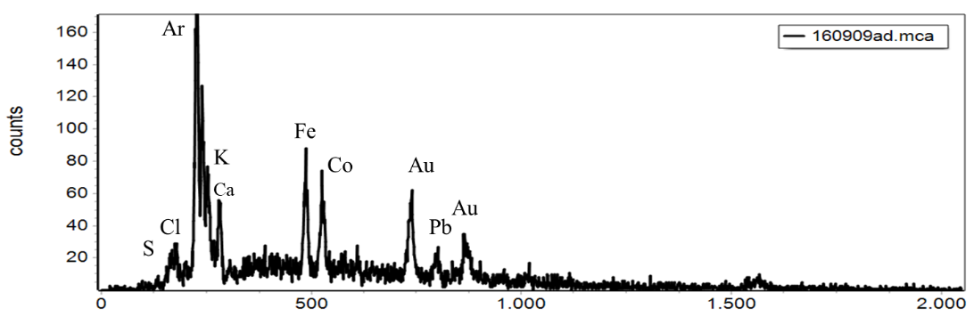 The energy level of the photon is characteristic of the element that emitted it.
XRF has been used for pigment identification.
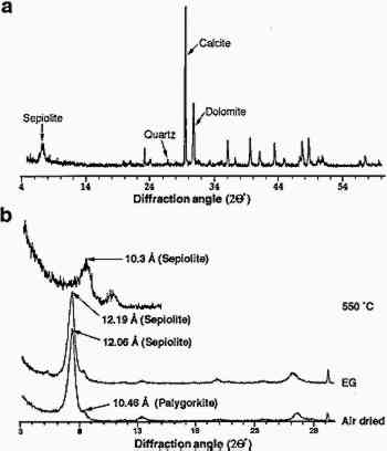
X-Ray Diffraction and X-Ray Powder Diffraction
These techniques are used to find the crystalline structure of a material and from that the chemical composition.
They have been used to determine the different mineral contents of limestone, pigment, and ground analysis of paintings and the identification of unknown crystalline deposits on objects.
X-Ray Diffraction and X-Ray Powder Diffraction
X-ray diffraction and x-ray powder diffraction are essentially the same technique, and you will sometimes find the words used interchangeably in the conservation literature.
- X-ray diffraction studies the scattering of x-rays from a single crystal.
- X-ray powder diffraction studies the scattering of x-rays from a collection of small crystallites that are randomly ordered.
X-Ray Diffraction: Crystal Structure
The individual atoms in many of the elements form crystal structures, or cells. Although very few of them are "ideal" it is possible to work out even complex molecules from the cells.

X-Ray Diffraction References
There are 14 different unit cells, called Bravis lattices, and it is beyond the scope of this unit to go into this in any depth.
If you are interested in studying this subject there are several books available that describe basic crystallography, including X-Ray Diffraction by B.E. Warren; Dover: Mineola, NY, 1990 and X-Ray Diffraction: In Crystals, Imperfect Crystals, and Amorphous Bodies by A. Guinier; Dover: Mineola, NY, 1994.
X-Ray Diffraction Diagram
If an energy in the x-ray region of the electro-magnetic spectrum is shone on a group of crystals it will be diffracted from the crystal planes.

X-Ray Diffraction Definition and Databases
Diffraction is the change in the direction and intensity of a group of waves (in this case x-rays) after passing by an obstacle or through an aperture (in this case the atoms on the sides of the crystal). The size of the obstacle has to be approximately the same as the energy's wavelength.
One of the largest databases (over half a million XRD patterns) is maintained by the International Centre for Diffraction Data (ICDD, www.icdd.com).
X-Ray Diffraction Example
In this example Rodriguez-Navarro et al. (1997) used powder XRD to determine the chemical composition of Egyptian limestone.
The "X Factors" (XRF, XRD, EDS)
In this section you learned about what I call "the X factor" techniques, which include:
- X-Ray Fluorescence (XRF)
(or Energy Dispersive X-Ray Fluorescence ED-XRF) - X-Ray Diffraction (XRD)
(or X-Ray Powder Diffraction) - Scanning Electron Microscopy Energy Dispersive Spectroscopy (SEM-EDS)
All of these techniques use x-rays to determine the elements present in an unknown sample or to examine the crystalline structure.
References
These articles have been used as examples in the text and can be found at JAIC Online.
References cont.
Schweppe, Helmut; "Identification of dyes on old textiles"; JAIC 1979, 19 (1). 14–23.
Final thoughts
This tutorial has briefly covered some of the most common analytical techniques you will find in the literature. We have tried to link them to the kind of research carried out in conservation.
It is very difficult, if not impossible, however, to give you a definite "list" headed "Strong Points" and/or "Limitations" for each technique. They overlap each other in so many ways.
Final thoughts cont.
For example, if you wanted to know the elements in an unknown sample:
- FTIR would give you some information
- Raman might tell you more
- Mass Spectroscopy (especially coupled with Gas Chromatography) would be useful
- EDX would (possibly) be best
In the end it very much depends on the analytical techniques you have available. To be honest, this applies to a lot of scientific research and researchers will often tailor their experiments around the equipment to hand.
Credits
Researched and written by Sheila Fairbrass Siegler
Instructional Design by Cyrelle Gerson of Webucate Us
Project Management by Eric Pourchot
Special thanks to members of the Association of North American Graduate Programs in Conservation (ANAGPIC) and the AIC Board of Directors for reviewing these materials.
This project was conceived at a Directors Retreat organized by the Getty Conservation Institute and was developed with grant funding from the Getty Foundation.
Converted to HTML5 by Avery Bazemore, 2021
© 2008 Foundation for Advancement in Conservation